


Web Site by cg-photohraphy.co.uk


If you have already read this preamble you can skip down to 30 May 2017 full project build.
Bench design, so what do I need?
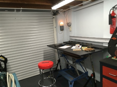
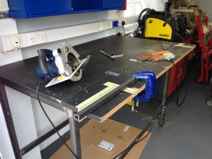
I already had a long 2.8Mtr bench in my garage, this was made by my late Father, unfortunately it was made as a workbench to sit at, for installation in one of my former houses in a spare room. I now need a bench I can work at standing up. Now my Father was a carpenter, this was a trait I sadly never inherited. I started out as an engineer, doing an apprenticeship, with the M.O.D. This meant that rebuilding the frame from wood for me, was a non starter. However, the bench top was fine, still in good shape after, 39 years. Has it really been that long?
Anyway, as an engineer I decide to remake the wooden, frame from metal, and weld it, as I have some experience of doing this.
Now some of you needless-to-say, are wondering why not just buy a new bench or two? So the problem with that is that you never seem to be able to find the right one. It’s a bit like needing a screw to complete a job, looking in all of your boxes, and just not having the right one, and then having to go out and buy some.
My solution, get some 40mm X 40mm X 3mm steel box. Purchase a welder, and make one!
I wanted to fabricate the bench frame in such a way so that I could, use things like, bench vices and grinders, but not have them permanently attached to the bench taking up space. Because, I wanted to make the bench multi purpose. One of my other hobbies is photography, and I wanted to make my own picture frames. So being able to remove items from the bench that I do not need is paramount to my design criteria.
Sliding, steel box sections, is the answer, more about this later!
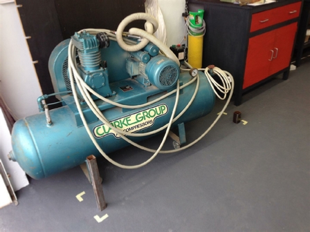
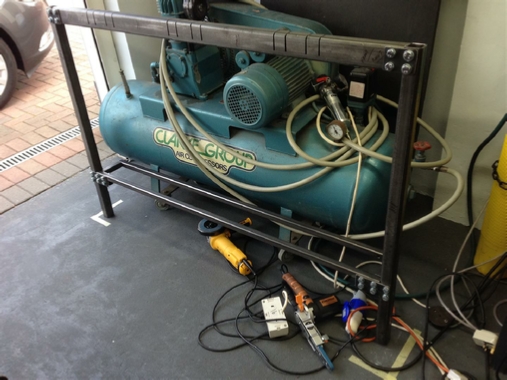
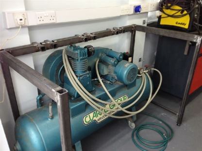
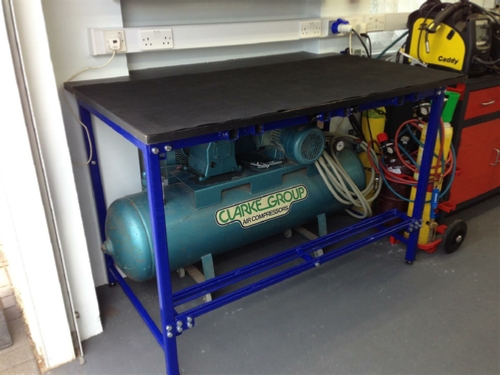
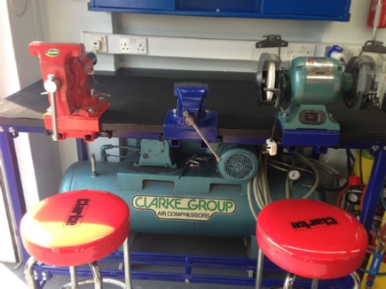
I decided on designing two benches, the first one needs to go over the top of my 14cfm Clarke’s compressor, that I purchased back in 1976 when I started to spray cars at home. It has certainly stood the test of time, no repairs since purchased, and I am also guilty of never changing the oil. Something that I must do! This first bench has got to clear the top of the compressor cylinder, which unfortunately means the bottom on the bench top will be set 98cm from the ground. Which is rather high, fortunately, I am nearly 6ft tall, so working on the bench, even at this height should not be a problem. However, the bench top has to go over the steel box section bench support structure, and this will add another, 40mm. So I am thinking that the front of this support will have to be bolted into place, rather that being welded. In this way I can wheel the compressor under the bench, then bolt the front section in place. So saving 40mm in height. This front section will also have to incorporate the sliding box sections. This first bench will be 1.5mts long and 75cm in depth. Which will give me enough area to do the glass cutting for the picture framing.
The second bench, will be 2.8Mts long, but be only 60cm deep. As the bench top was original for a kitchen work surface. One very good thing though, if you design and build your own, you can incorporate into the design whatever you need. So my design will incorporate the same sliding steel box section from bench one, so that I can use the same vices and bench grinders from bench to bench. This second bench will also incorporate a sink, because I want to investigate removing rust using electrolysis as well as electro plating. There will also be a requirement to add an electric 10kva boiler so that I will have hot water.
Bench Design & Build
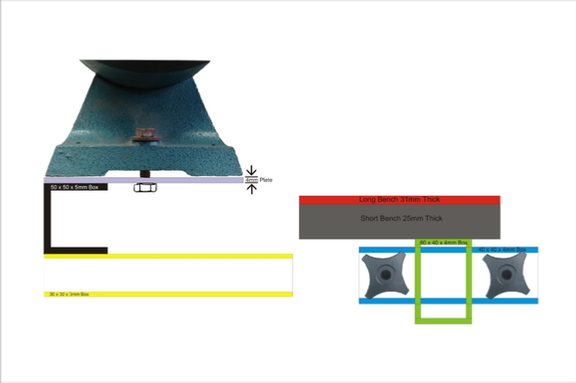
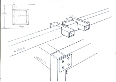
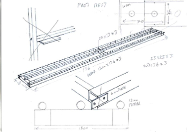
It is now the beginning of December 2016, it’s getting too cold to continue with the workshop, however I can continue with the bench design phase. Below is that first design of the quick release mechanism, which will allow me to move things like the bench grinders or vices around. Completely detaching them if I want a completely flat bench to work on. The design is in 2D, but I have now purchase a 3D drawing board. So I will add some 3D drawings after Christmas, as the board is going to be a Christmas present from my Mum!
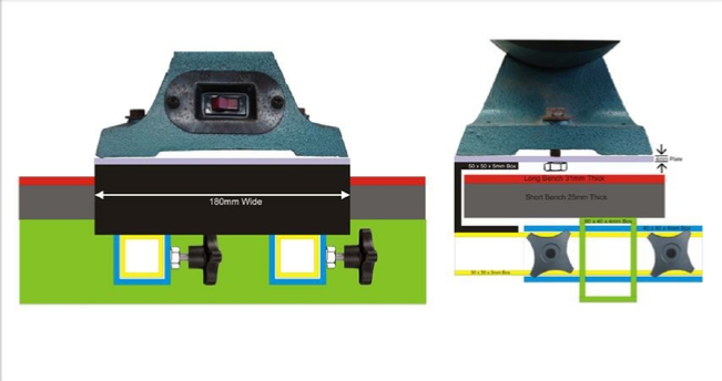
The pictures above show the mechanism from the front view and the side view. The double bench height is because the 1.5Mtr bench and the 2.8Mtr bench's are different heights and the same design has to work for both.
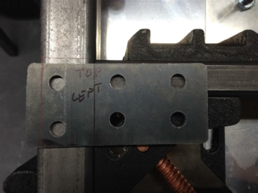
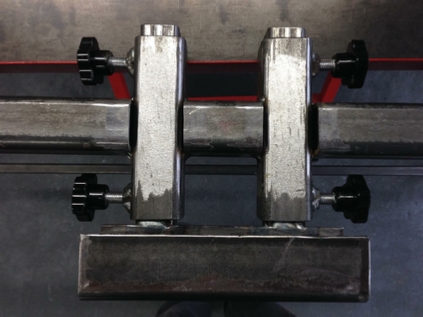
The second picture, shows the two parts of the sliding mechanism, but this time in two parts, the first part attaches to the removable device, the second part is attached to the steel infrastructure of the bench. The unit that is attached to the top half of one of my Black & Decker bench grinders. The picture below, shows some of the other parts that I have purchased ready for the finished bench design, prior to building.
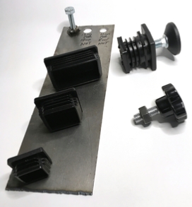
At the top of the steel plate, you can see one of the ‘weld nuts’ that has been welded on, screwed into this is an 8mm bolt. This will be used to attach the bench grinder, or one of my bench vices to the sliding mount. Also on the steel plate is a selection of plastic tube ends. At the top is the 60mm x 40mm, followed by the 40mm x 40mm, and then the 30 mm x 30mm.
On the right of that is one of the feet, screwed into one of the 40mm tube mountings.
Underneath that is a 10mm Star Handel that will be used to tighten the sliding mounts to the bench.
The picture below, shows some of the other parts that I have purchased ready for the finished bench design, prior to building.
I am planning to redraw the 2D design above, using my new 3D drawing board, and present it here on the website. The specialist board was purchase in the UK from CR Clark in Wales. Unfortunately since my purchase this board has been removed from there website? So this is the link to the same board from Designability in Australia.
A demo of the 3D board can be found below:

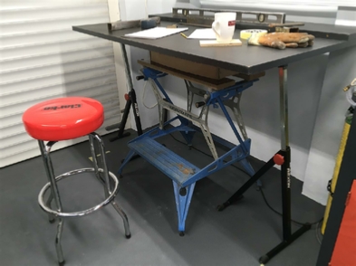
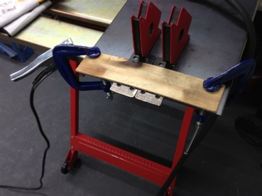
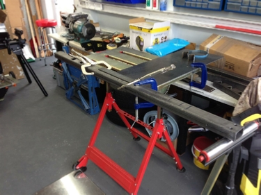
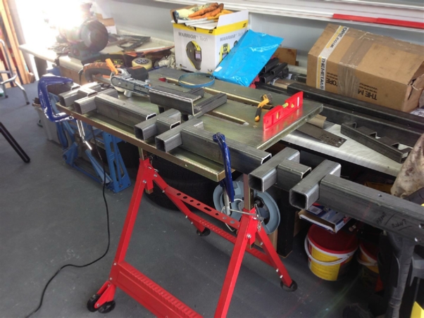
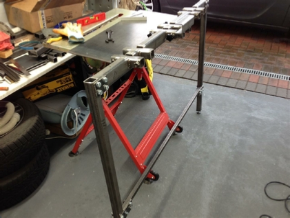
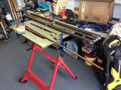
This is the big one, my first large project. First of all I needed to get some idea of what I wanted. I knew that the Bench must fit over the compressor and that it must include those quick release mounts. So I made a mock-up by using my Workmate to hold the wooden bench top in position at the right height. I ended up using my trolley jack box on top of the workmate because it was heavy and would hold the weight of the bench top, I also added my two roller stands for support on either side. See the pictures below.
If you have a look at the picture, you can see my mug? to be honest sitting on the stool this bench was super comfortable, and one feature that I did not count on was the bottom part of the workmate which acted as a footrest. I just have to add this into my design.
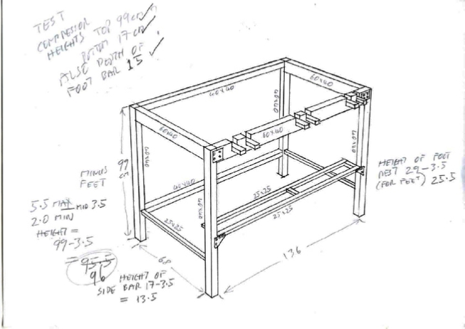
I did had some doubt about that size of the steel that I decided to use. But first lets look at the overall design, using my 3D drawing board of course.
One problem albeit a small one, is what was I going to use to stop my feet from sliding off of the footrest. Then I had an idea, how about Rebar, it has a slighting sharp texture and is cheap as chips!
Now remember the front cross member and now the footrest, must be unboltable, so that I can get my compressor out for servicing. That will mean creating some steel plates or ‘fish-plates’ as I call them, they were used to hold the railway lines together before they welded them.
I feel the need of a plasma cutter coming on!
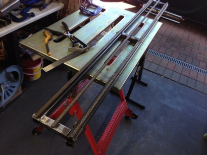
I did make some measurements using two pieces of scrap steel on the workshop floor, just to make sure that the compressors would go in and out ok.
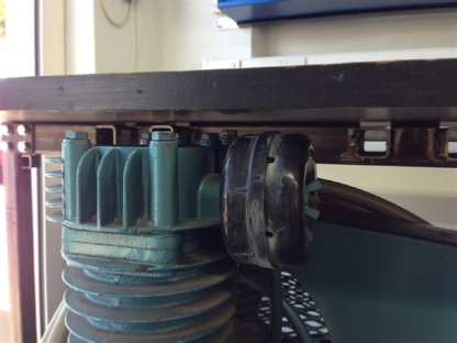
One other criteria was, that the front to back cross members must be low enough not to foul on the compressors air tank.
Below are some close ups of my design. The picture on the left is of the quick release mount, and the one on the right is of the footrest, including that rebar.
We now have the design, but this is a ‘design and build’ as architectures like to call it. That is when some aspects have to be changed on the fly. Now CorelDRAW is my favourite 2D Cad/Cam program and that is what I am going to use to draw the fishplates. I want to get these correct especially when you are drilling holes, and you need to get it just right.
So how to go from CAD/CAM to plasma cutter, this is the question? Then I saw this video:
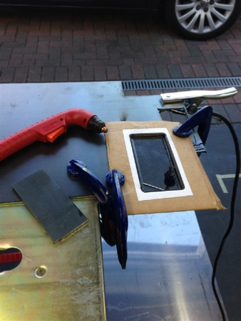
So I thought why not, nothing ventured. So I got going with the CAD/CAM and printed off some template sheets, stuck that on some corrugated cardboard, cut them out with a scalpel, set the Cros-Arc to 31 Amps as I was cutting 4mm steel plate and…..
now hang on I hear you say, are you actually going to use a plasma cutter with a cutting temperature of nearly 30,000C and cardboard! Well yes I am. What can go wrong?, and remember I always have the fire extinguisher on the wall!
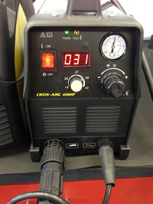
5…Cros-Arc set 31 amps…
4…Air pressure set 65psi…
3…Shade 5 Face shield on…
2…Fireproof overalls on…
1…Tig Glovers on…
and here are the results….
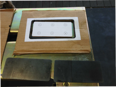
And no I did not burn the workshop down or need that fire extinguisher.
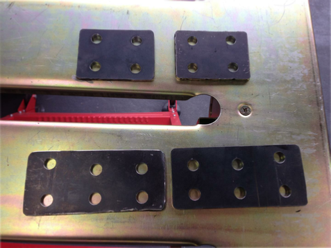
The finished plates now drilled, and looking ok.
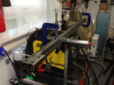
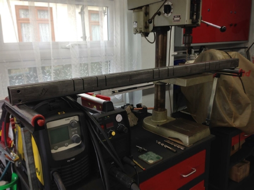
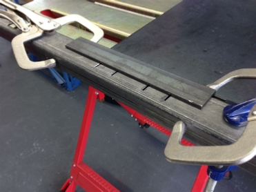
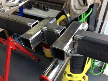
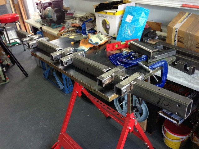
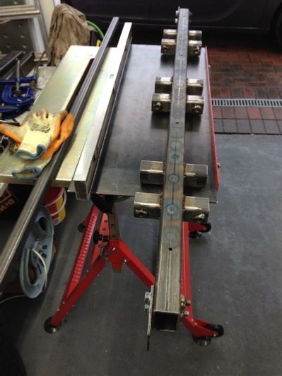
Next up, that front cross member. I needed to make the cuts for the 40 x 40 box section that was going to get welder to hold the quick release mounts. These cuts must be as accurate as possible using my Rage 3 Saw so I made up some cutting guides. Using some steel plate and some weldnuts of course. Have a look below:
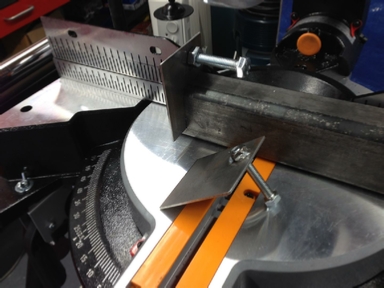
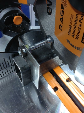
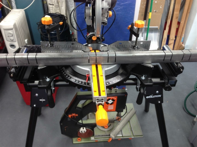
All of the cuts needed to be at the same depth, and parallel, as the sliding mount parts would be square as I was using a jig to make them. I now needed to think about how the ‘fish’ plates were going to be used and line them up so the I could drill the bolt mounting holes.
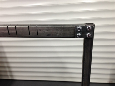
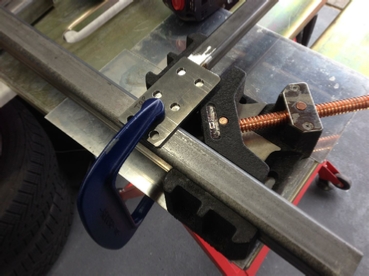
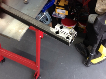
First set of ‘fish’ plates drilled and fitted between front cross member and front legs.
Next up that footrest
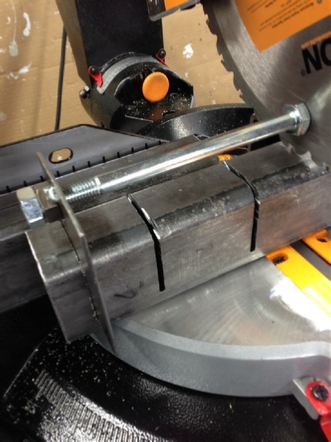
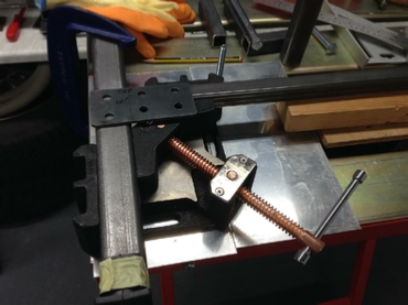
Set up the wooden guide, and cut away, and the job is a good’un!
Notice the right angle clamp in use, above left, and remember I said this was a design and build? Well I decided to shorten two of the ‘fish’ plates. No problem with a plasma cutter.
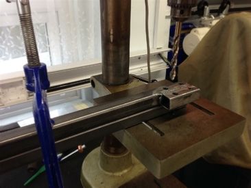
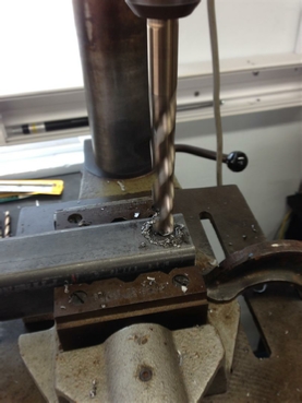
Time to start work on that footrest. Drilling the ‘fish’ plate mounting holes.
Time for a fit up!
Drilling the bench top mounting holes in the front cross member. Notice both extended roller stands being used.
Its now getting serious, I have to plasma cut the cross member to be able to fit the quick release mounts, one slip here and I am done for! I need to fire up the Cros_Arc plasma cutter for some 5mm cuts.
Well I am glad that it is now over with, however no drama with the Cros-Arc fired it on 40amps and away we went. Looks good!
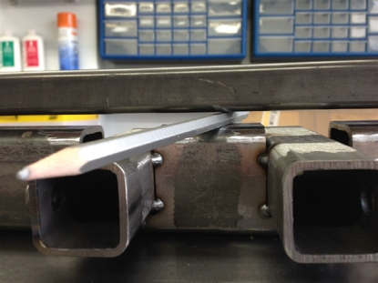
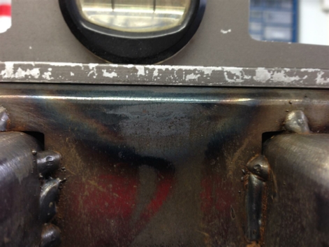
Now I needed to make sure that when these pieces were welded to the front cross member they would be level, so I needed a ‘cunning plan’ as Baldrick would say.
So I set the spirit level on the cross member and noted the bubble position, I then filed down that part of the cross member that I have just plasma cut with my Evolution electric file. It was quick and simple, ‘I love it when a plan comes together’ now who said that?
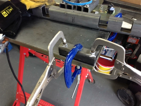
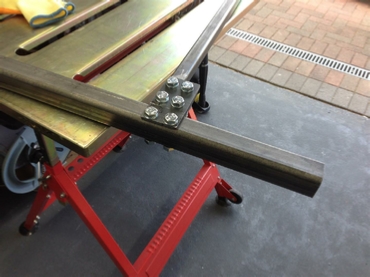
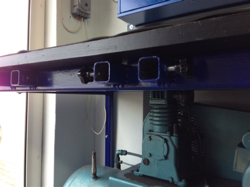
Ok the cross member is now done, time for those weld nuts. I am using star wheels to lock the quick release mounts in place when is use. Simply drill the right size hole, clamp the weldnut, after locating in the hole, and weld it. Job done.
I now need to start welding the quick release mounts in place to the cross member.
This is where I take some issues with other people and their welding. Not because it is not neat and tidy, but lots of people tend to over weld a project, and get heat distortion. Now I know the tricks, don't weld continually, go here and there, then come back to where you started. But you are still over welding. Does that seam really need to be completely welded?
Now don’t get me wrong, if this is structural, on a building, or a car chassis it is totally different. But most of the projects I do are not that sort of thing. So I tend just to tack weld. However, you MUST if using this technique get enough penetration. Luckily my ESAB has its own synergic settings, so getting this right is easer than clicking a couple of switches on a welding chart, and hoping for the best.
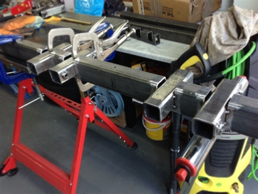
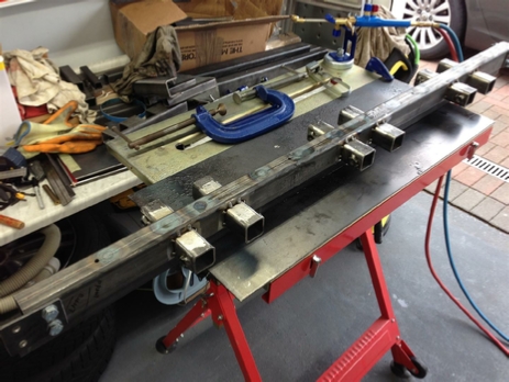
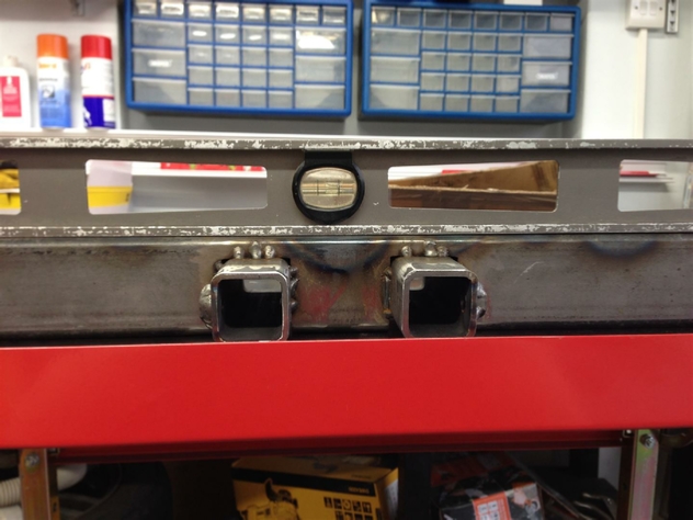
So tack welding is what I did, as you can see below.
Now you know that there is a but coming up…But despite my tack welding, the front cross member still bowed by 15mm over its length. Oh S***.
Now 15mm does not sound too bad until you realise that this is going to be the main stay of the bench and remember all of those bolt holes and fish plates? Not to mention that 35mm thick wooden bench top. So at this point what should I do? Scrap the front piece and start again? or try to fix it? Its 5mm thick mild steel, it’s no good standing on it, that won’t work, what about a 20 ton press?
A quick bit of research suggests that heat bent it, so heat can strengthen it, right?
I looked at a article about what the shipwrights did back in the 20’s, and found a interesting information on ‘Heat Straightening and ‘Flame Quenching’, that sounds like fun!
Only problem was ‘how do I precisely heat a piece of steel that big’? and get it to a minimum bright orange temperature?
Now if you remember I was looking at using HHO. The problem with this is that the generator to create enough HHO would cost about £1,200 and be over 1Mtr in length, nearly that same size as my compressor. The other problem would be the temperature. HHO is a fantastic product but can only reach about 2,800C the other problem is that the flame is oxidising, which would be no good for welding. Whereas Oxy-acetylene can reach nearly 3,500C and can be set as a neutral flame, and so is perfect for welding.
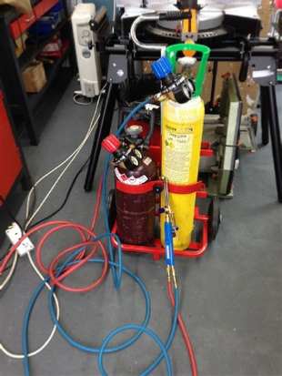
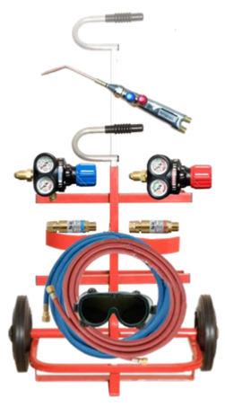
So decision made. I looked around for a suitable oxy-Acetylene kit. Now I already know that I would need a cutting torch. Not because I needed it for cutting, as I already have a Plasma for that. But because I would need a very concentrated heat source, a spot heat source in fact.
Now for the two processes I was about to try, you DO NOT need to use the extra oxygen trigger on the cutting torch, because if you did you would simply cut the steel in two. You also must NOT use a ‘Rose Bud’ touch as the heat it produces would not be localised enough.
This was going to be fun, filled with trepidation, and a little bit scary.
I did not want the time, money and effort that I had spent so far coming to ‘nowt’, and be incinerated in an instant!
As you have already seen I purchased my Oxy-kit from Welders Warehouse. I observed all of the safety requirements as I have already outlined when setting it up.
So I was ready to go!
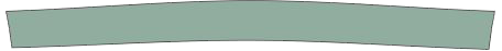

This is obviously how the cross member should look, as seen from the front.
Nice and flat and level.
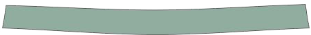
This is how it looked now, the heat from the welding had bowed the top, despite my best efforts, of only tack welding it.
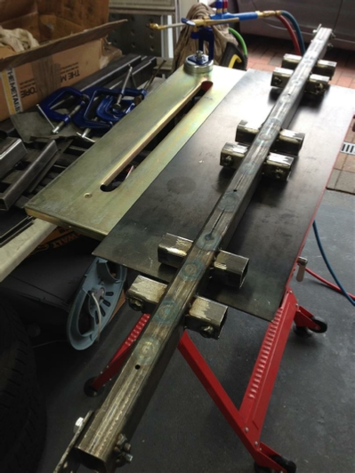
So the theory goes, by heating it in the centre and then at equal distances left and right in the centre of that distance each time, what I am trying to do is heat stretch the bottom of the cross member bearing in mind that it was 5mm thick and 60mm in height. In that way I was hoping that it might go back to being straight? So take a look at the order of the numbers below, this is the sequence that we are going to use.


We are going to kick-off with ‘Heat Straightening’, and after applying the heat to position number 1 I am going to use an ‘Air Gun’ to rapidly cool the surface of the steel that I have just heated. I then leave the cross member to return to ‘hand temperature’. Re-test the steel for being straight by using a long piece of 25mm sq box section. Then start the process again at the next position, in the case 2 and so on.
So what next, well this is the big one!
‘
‘Flame Quenching’, so hold on to your hat!
Flame quenching is rather violent, no it does not involve hitting the steel with a big hammer until it shouts ‘I surrender’, it is worst that that!
It involves heating the steel until nearly white hot, and then..wait for it, pouring on cold water! So now you know.
The theory is that the steel will expand with the heat, and then hitting it with the water, will rapidly cool so quickly that it cannot return back to its original state. This will then leave it longer than when it started. Which is exactly what we want, and remember we are only doing this on one side on the box section, the bottom.
Now for this is work, you do not need a hosepipe or anything like that. I just used an old squeegee bottle, you know the type of thing, that you have in the kitchen that you use to clean you counter tops. Empty it out, wash it out, and then fill it with cold water, you are then good to go.
This process is also much more brutal on the metal and I wasn't sure what was going to happen?
Well you know what they say ‘anything can happen in the next half hour’ and this time it just might!
I started off following the same number sequence as I did the first time, as the front cross member was now completely cool.
It was fun but a bit scary spraying cold water onto white hot metal.
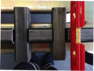
So at the end of the process, after about an hour or so, how did we do?
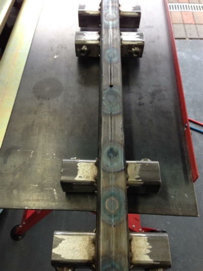
Well as you can see we are getting there, we are down to about 4mm from about 15mm.
I followed the number sequence to I guess about half way, when suddenly….there was an almighty BANG, like firing a shotgun without ear defender on, and I thought WT*. I then thought oh well its most probably fractured the steel, or one of the welds has come apart, but wait it all looked ok… very strange.
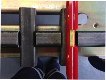
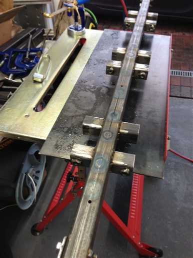
So I checked it with my spirit level,and…
I also checked it with my long 25mm box section, and it was completely straight, and I mean completely. So it would seem that those shipwrights back in the 20’s did know a thing or two….
The video below is just a quick iPhone capture of the moment.
I needed to make sure that this cross member was not lying to me! so I bolted it up to the footrest rail and all was ok. I then tried using the Quick Release Mount, and guess what? That also worked perfectly. Time to move on and complete the two side legs, and that footrest with the rebar.
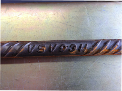
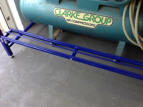
Rebar is your friend?
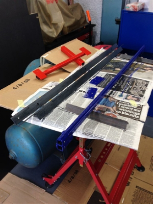
I spent some time looking around for the right thing to use on the footrest to stop my feet from slipping off. In the end I decided on using, most probably, the cheapest thing you could buy some Rebar. The surface is very rough, maybe even slightly sharp, so that the concrete will ‘stick’ to it, so perfect for your feet. Its also steel so it will weld! Job done!.
I told my steel suppliers at The Metal Store that I needed it supplied flat so they laid the rebar onto a piece of wood for shipping to me. Very helpful as the three lengths arrived perfectly flat. All I needed to do was clean the surface rust off that had accumulated since it arrived in the workshop.
I must say that ALL of the metal that they have supplied to me has arrived in first class condition, none with any rust. Well done The Metal Store!
Welding the Rebar in place, despite reading some concerns about it welding, mine went in perfectly.
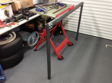
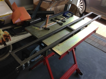
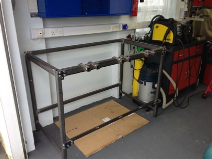
Doing a quick check to make sure the front cross member and footrest bolted in ok, and placing part of the bench top in place to check the width fitting.
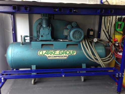
Remember those side bars, they had to be low enough to allow the compressor air tank to clear.
The bench for this test, was put in back-to-front just to check those clearances, all checked out ok!
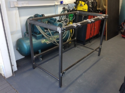
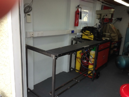
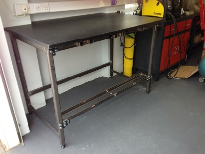
The back panels are now welded into place. It now starts to look like a bench frame. It certainly feels like one, as this now weighs in at 120kg! With the top fitted and bolted into the wall it’s not going to move anywhere.
So lets drop the bench top into place and check that all important height clearance. If it’s too low the compressor won’t fit.
Looks like we are ok!
Frame now bolted into the workshop wall remember those Coach screws and Fischer Universal Plugs? I thought initially that I had used steel that was too thick and heavy, but now, feeling how rigid this bench frame sits bolted in, I think that the choice was definitely right.
The wooden black bench top that I am using is from a computer bench that I used to use. Notice the fixing plates, where I joined the two pieces together, to get the depth of about 1Mtr. The two pieces are also doweled and glued.
Bench top now cut and bolted into place.
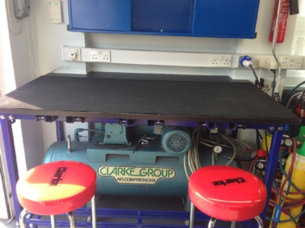
It’s finally starting to look like a real bench!
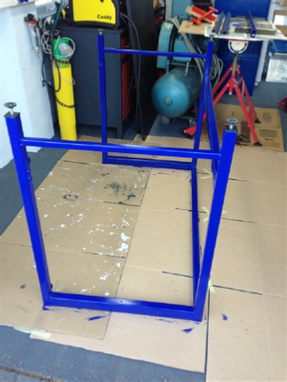
A quick coat of paint and Hey-Presto!
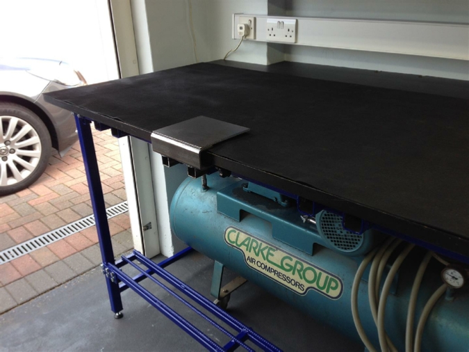
I have to say that two years on, this bench has lived up to all of its expectations. I have removed the compressor to change the oil, and also removed the bench top and frame to get those alarm wires shortened. The other thing that you might be interested in, is the rubber covering that I placed over the wood. It was from one of my favourite shops Machine Mart. I wanted a covering that was impervious to oil and most materials that I was going to use, there Rubber Matting - Ribbed is 3mm x 915 x 5Mtrs currently sell for £35.98.
Here is a secret, turn it upside down so that the ridges are underneath, that will give you a non slip surface (facing down), and a smooth surface on the top to work on.
I have this fitted to my Lathe table, Drill table, including inside the drawers, also in my Blue Wall cabinet. Try it! You won’t be disappointed.
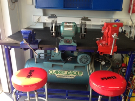
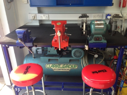
The final picture above also shows one of the Quick Fit Mounts fitted in place.
Now the pictures below are a sneak preview for you of the finished mounts being used showing their versatility.
All of these mounts are featured in the following site pages.
I will leave you with the pictures, another project finished!
First of all we must turn the cross member over, and apply heat from the opposite direction from how it was welded. In this case the bottom.
We now have a finished bench.
Project Date: 30 May 2017
Preamble Date: Sep 2016
 Next Project
| Rage 3 Saw |
| ESAB Welder |
| Cros-Arc Plasma |
| HHO |
| Spot Welding |
| Betty's Gates |
| Car Headlights |
| Julia's Dartboard |
| Outside Light Base |
| Weather Vane |
| Geoff's Gates |
| Loft Hoist |
| Colin Laser Mount |