


Web Site by cg-photohraphy.co.uk


As you might well know, we live in a Bungalow. When we moved in, about 13 years ago, it became obvious to me that the loft space was very useable. I am 6ft and can stand up very easily within the space. So with this in mind I had the Carpenter board out the entire space with 22mm tongue and grooved board and screw it in place.
Now as the Bungalow was build in 1932, unlike modern buildings, it actually has internal solid brick walls. Which if you have anything heavy and you place these items in the loft but above where the walls are, you should be able to use this space safely.
One other thing I had the Carpenter do was, as we had to replace all of the ceilings, asked him to enlarge the loft hatch, so we could make better use of storing larger items up there.
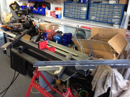
Why am I telling you all of this? Well, over the last couple of years, not only have we acquired lots of items for Julia's Boot Fairs, but also some items that I have been unable to store in the loft space, as they were too heavy to lift up there.
I have two amplifiers, a microwave, and also acquired a second large inkjet printer. All of these items need to be stored, and can go into the loft except they are too large and too difficult to get them up there.
This problem is only going to get worse as we get older, some sort of hoist would be a good idea and that is what we are going to do!
Loft Hoist
Project Date: 3 Dec 2018
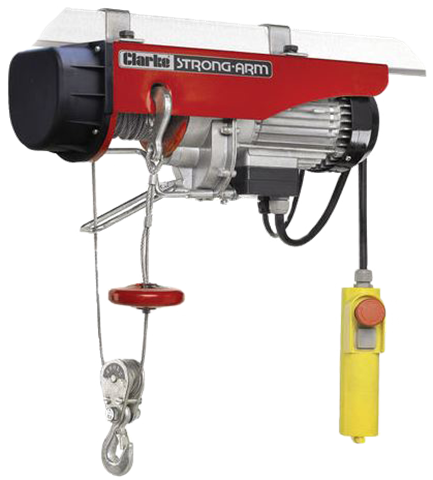
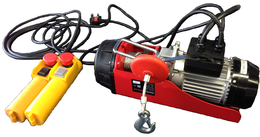
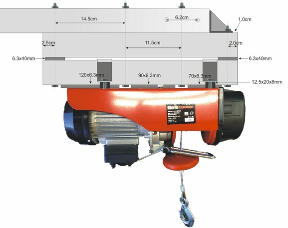
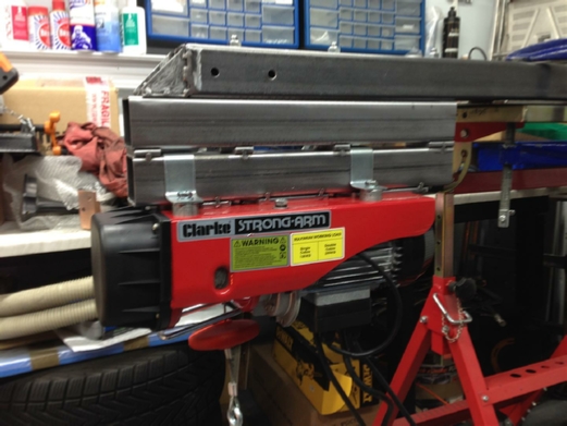
I waited until one of those VAT free cards came through the post from one of my favourite stores Machine Mart, as they had a 125/250Kgr electric hoist which would be ideal.
You can view it here: Clarke CH2500B.
You can also view the .pdf Manual here: CH2500-CH4000.
This hoist can lift a maximum weight of 250Kg (if you use the supplied second pulley wheel) which equates to ¼ of a Ton, even if you don't use the second pulley the lift is 125Kg which equals to 19.5 stone so could lift me with ease!
In reality you do not need anything any larger.
This project has some very special considerations, namely safety.
We are going to be constructing a steel structure that will have to be attached onto the loft rafters.
All of the weight we are going to lift, plus the weight of the steel, will then be transferred into the roof structure.
This has got to be right, because we could collapse the whole roof, not to mention someone can be injured or even killed!
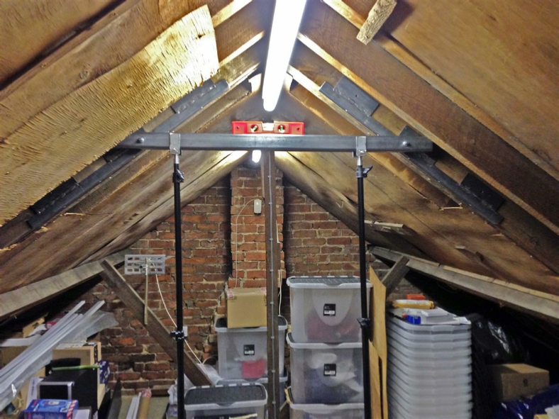
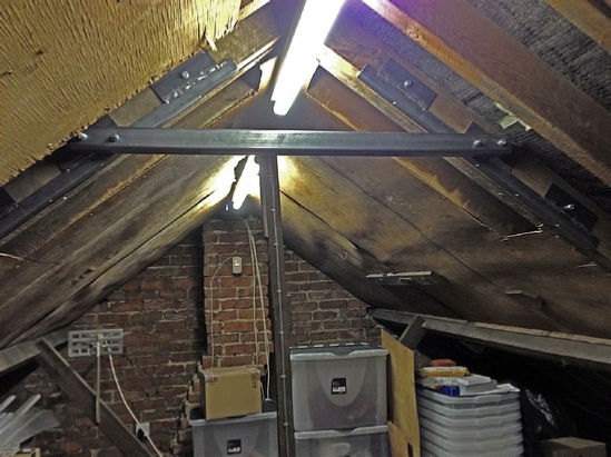
Let’s take a look in the loft.
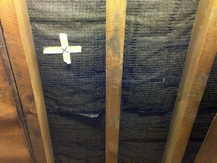
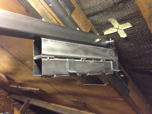
The former owner Tom, added plywood to the rafters, I suspect he did this to help stop any dust that blows in under the roof felt.
I have removed one of the sheets, and you can see that cross, which is where I would like the hoist pulley to lift from.
Now if you look at the far left you will see two rafters together, that is excellent as I need to place the high tensile steel bolts there to take the weight of the hoist, and two rafters are better that one as they say!
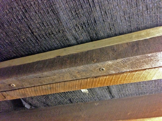
Unfortunately, things did not turn out that way when I removed that plywood covering up the second rafter, as I then discovered that it was only half the rafter I thought it was, literally.
The main roof rafters are 2” x 4”, the second rafter is in fact only 2” x 2”.
Why? I have no idea.
Houston we have a problem? As they say.
Anyone knows that if you are going to place bolts though wood you MUST place them through the centre, which is the strongest part.
In this case we can’t because there is no centre, so we need a cunning Baldrick plan?
In this case we must supply a second 2” x 2” rafter, and pin it to the first, in this way we can then drill through the centre without any problem. Take a look below:
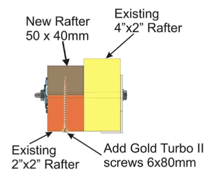
The plan is this, cut some rafters, that are 10mm short in width, so won’t but up against the roof felt.
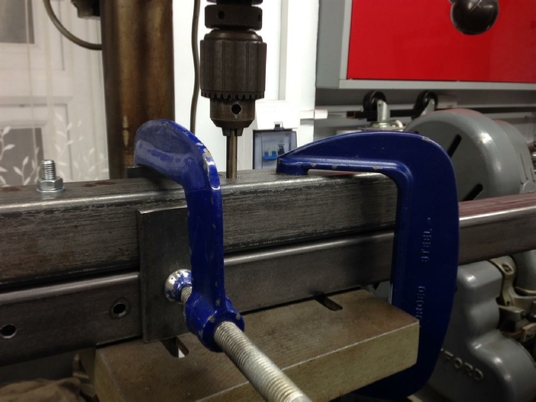
As we are going to use large 6x80mm turbo screws we MUST clamp the new rafter to the old one.
That might be another problem as we can’t get a G-clamp in there?
I also wanted to stop those high tensile steel bolts coming loose, so we need to find some larger washers as well?

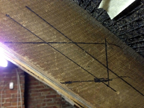
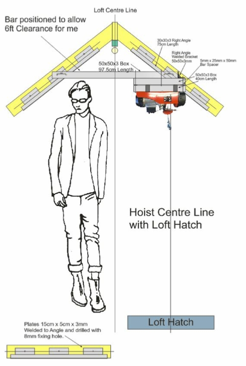
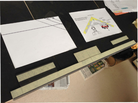
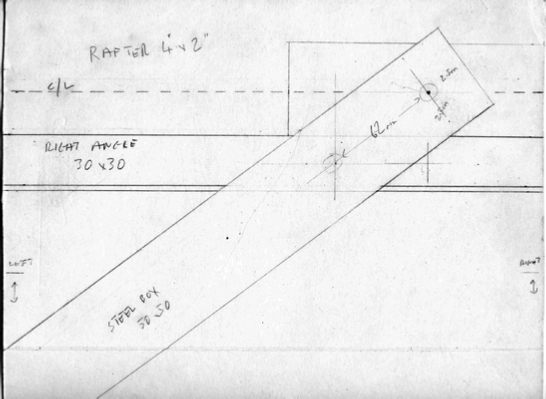
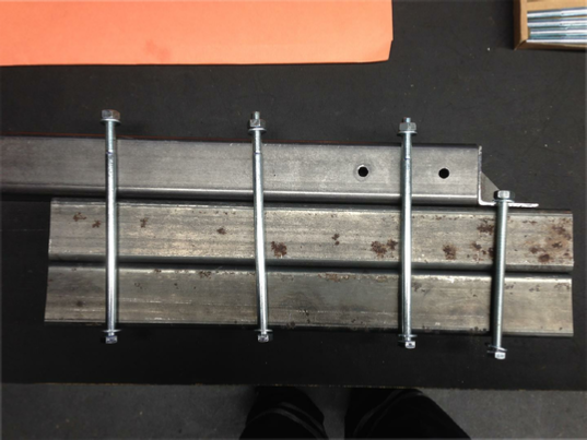
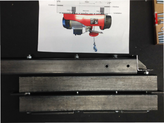
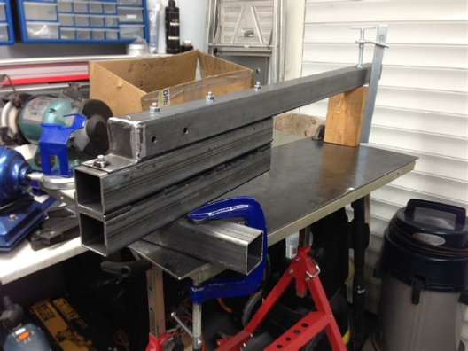
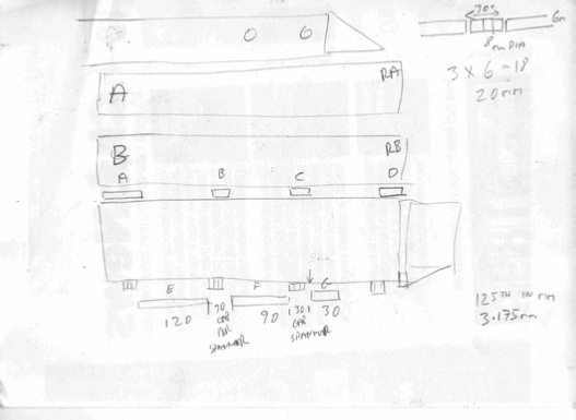
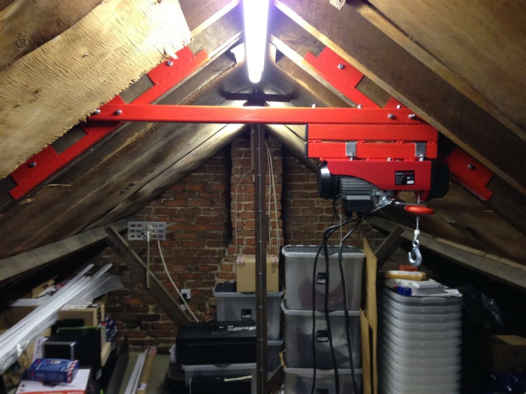
Things are starting to come together, I worked out the angle of the rafters, and marked out where the cross beam needs to go.
One very important design consideration was that I wanted to be able to walk under that cross member, however, I needed to lower the hoist fixing point, so as to allow the hoist winch to be over the centre of the loft hatch. Take a look at the CAD/CAM drawing below.
This is what we are going to do.
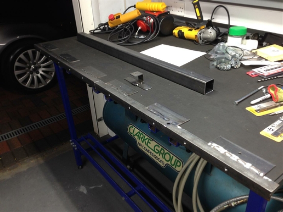
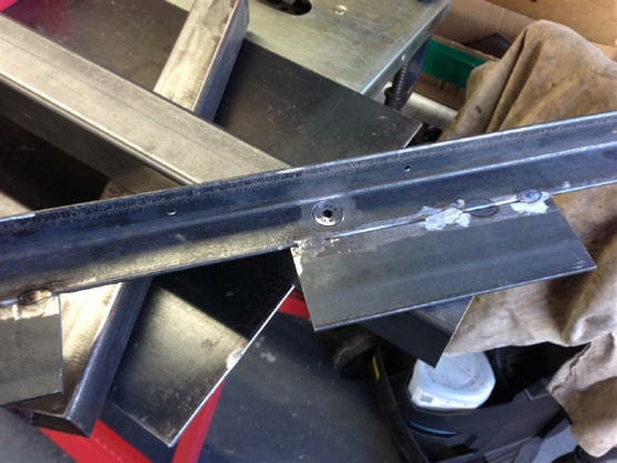
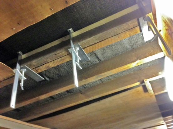
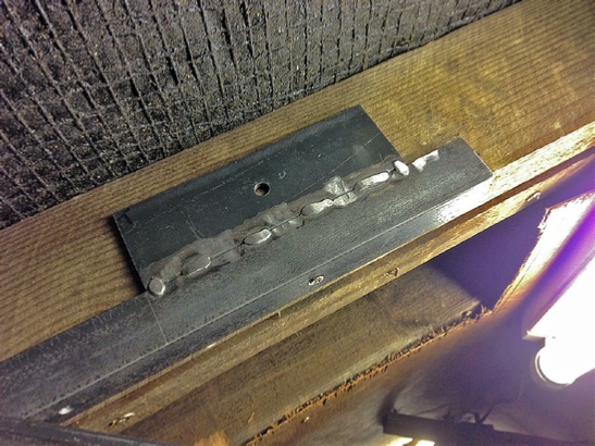
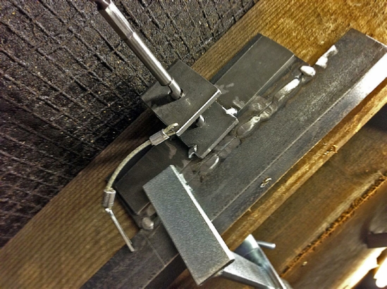
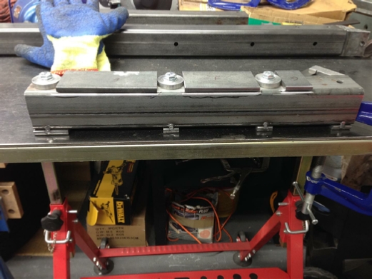
When those extra rafters are in position, weld some plates onto some angle iron.
Bolt one set to the left, and one set to the right. Position a length of box section between the two double bolting it both to the rafters, and to the steel angle iron. So any lifting weight is spread as much as possible.
This is very important.
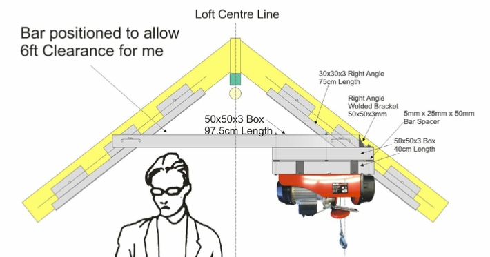
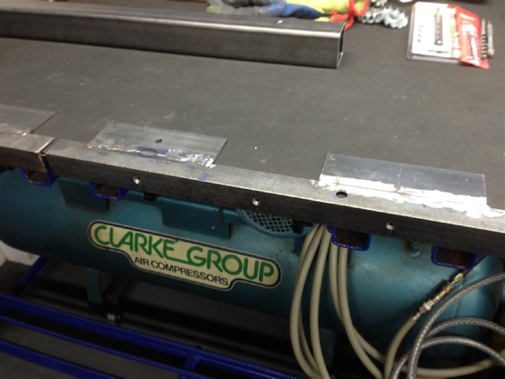
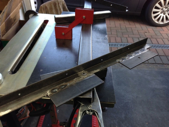
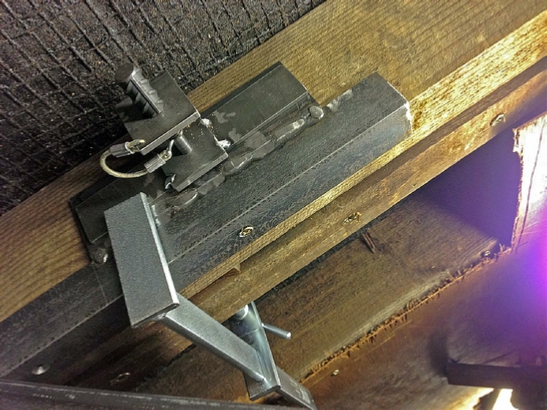
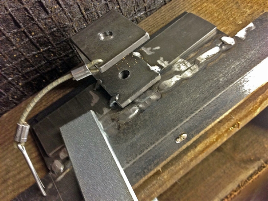
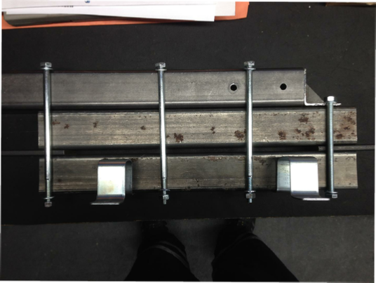
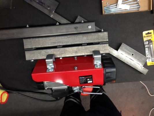
Close up detail from above
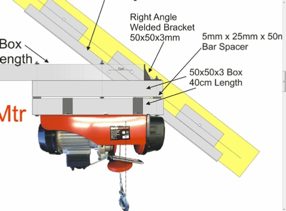
and the hoist detail
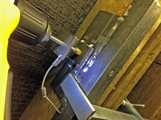
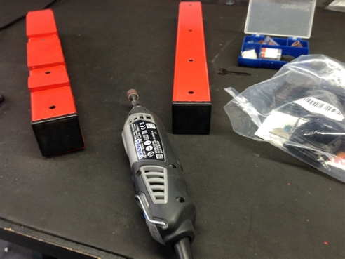
The design is coming together. Let’s look at some of the tools and parts that we are going to need.
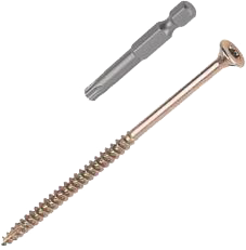
First of all those Gold Turbo screws 6x80mm from Screwfix, I decided to get the version with the free TX bit, for more driving torque, rather than the Pozi bit.

I wanted to spread the load when I tightened the high tensile steel bolts through the wood, and so decided to use ‘Dog’ washers which would ‘dig’ into the wood. Found these on Ebay.
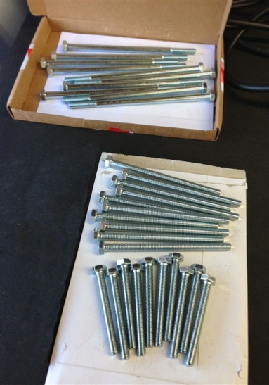
Needed some very long high tensile steel 8mm bolts.

I also needed some wood drills, these would hold themselves better in wood and cut better than steel drills. I purchased three in different lengths, as I have to cut through 4” of rafter in one go.
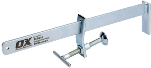
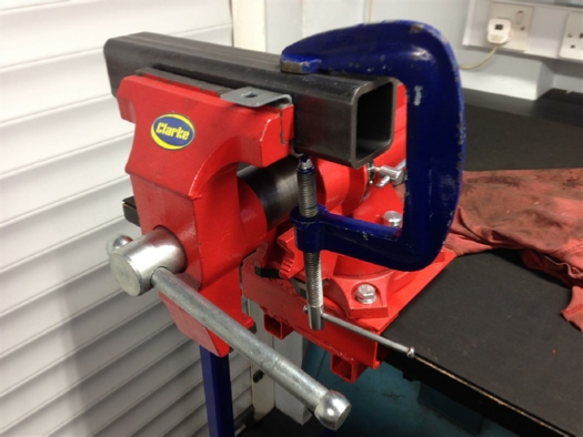
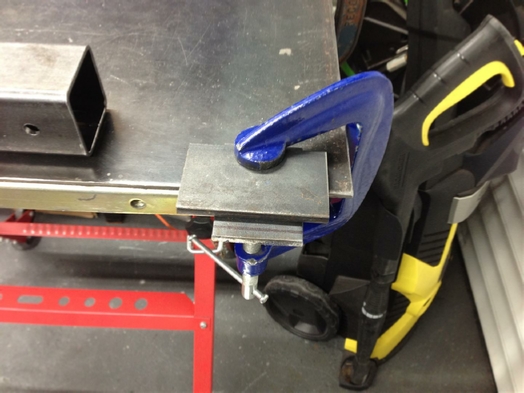
I also needed to find some clamps with a very short head space. A G-clamp would not work, as I only had 10mm of space between that new rafter and the existing roofing felt.
I then found these, which are bricklayers clamps, and purchased three of them. They are Pro 330mm Sliding Profile Clamps from Ox Tools. Ebay.

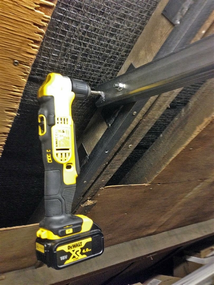
I also purchased one of these DeWalt right angle drills, because the rafters were only 24cm apart, and there was no way a normal drill would fit, along with those long 8mm brad point drill bits.
Ok, that’s got some of the parts buying out of the way. Now for something more practical.
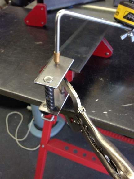
How am I going to hold those steel parts in place while I drill the holes through the rafters?
Because it’s going to be one of those ‘hold it in place’ drill jobs, rather than one of those ‘measure, make in the workshop and then fit’ jobs!
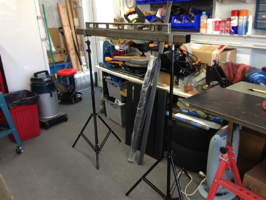
Now I have some photographic stands, these can easily hold a steel pole, and a large roll of vinyl for a photographic backdrop, so holding the steel cross member is easy.
All I need to do is make some adaptors to go between the steel box section and the stands.
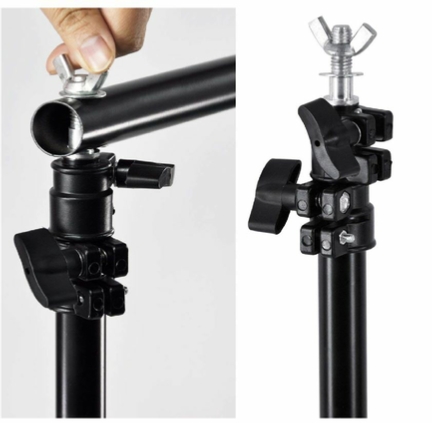
This is the fitting on the end of the stand.
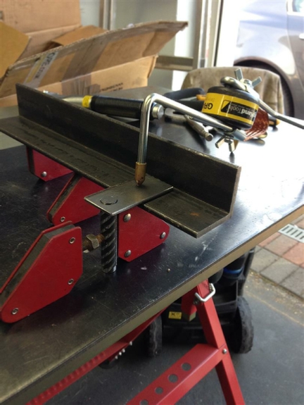
Using a Grasshopper and some magnets to hold the second end plate square before welding.
The design is simply, a small piece of Rebar, just used because it had a pattern. Tap a thread in the centre to match the thread on the end of the photograph stand.
Turn down both ends of the Rebar in the lathe, to match holes drilled into the two end plates.
The distance that the end plates fit, are a match for the 50mm box section.
Getting the right height set to keep the first end plate square.
Both jig’s finished and being test fitted on the photographic stands.
Close up of one end.
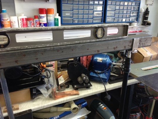
Easy to set level, as the stands adjust for height.
One job done, now for those Dog washers.
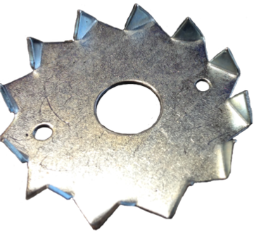
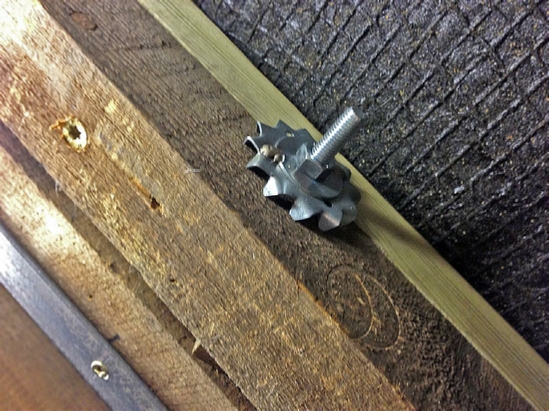
This is a M12 x 50mm Timber Connector Dog Tooth Washer.
One thing you will notice is that the centre hole is far too big for an M8 bolt to centrally locate.
So we will have to fix this first, and I feel another jig coming on, and I don’t mean a dance!
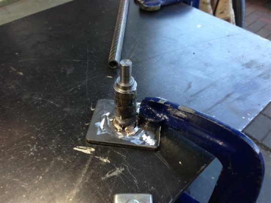
..and here it is. This will hold the Dog washer, and an M8 washer together, and centralised.
However, I am not going to weld them, but MiG braze them instead.
Why? Because I do not want the heat to burn off the zing coating, and brazing works at a much lower temperature than welding.
Braze will also not rust as it is going to be within the loft space, like an untreated weld might.
It’s just a piece of Rebar, turned in the lathe to hold both of the washers, welded onto a small square of steel acting as a base.
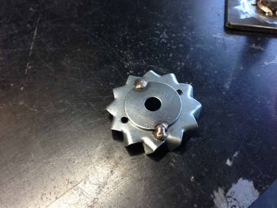
First washer finished.
I turned a second piece of Rebar to act as weight, to hold both of the washers together.
Nearly finished. The time spent making a jig was well worth it, to get a constant finish.

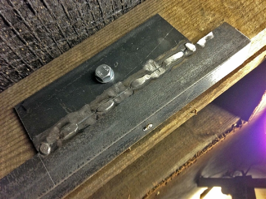
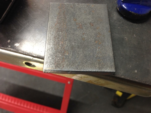
Marking up the angle iron and steel plates prior to welding them.
Angle iron and steel plates welded.
Welds must be ground off as much as possible without weakening the structure as the cross section box must be bolted on to it, over the welds.
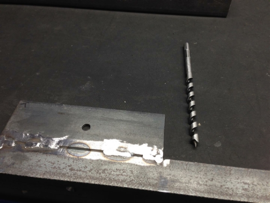
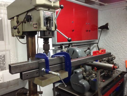
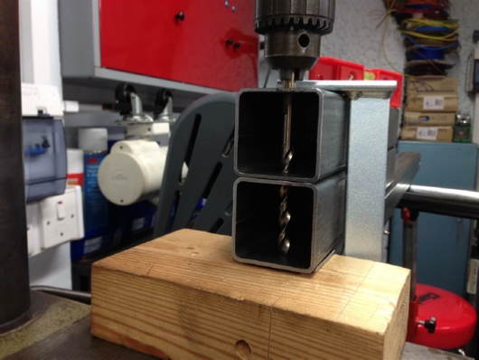
Now this is another problem. We have to drill into the rafter, and this is going to be about 5” in depth.
How do we keep the drilled holes straight? Bearing in mind the we will be using 120mm M8 bolts.
I fear another jig is needed, and this one is going to be amazing.
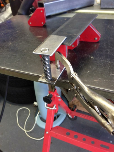
So what we have is a steel plate, welded to some angle iron that will be clamped over a roof rafter, that we need to alight with a drill.
The plate already has an 8mm hole that we must align with.
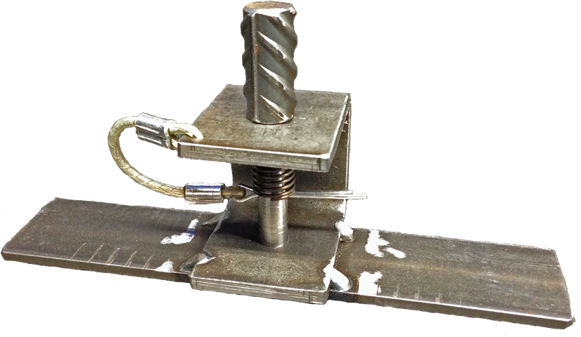
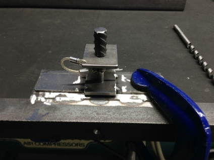
And this is what I made. We have a C section steel piece welded to a clampable base.
The plunger is sprung loaded into the downward direction.
1) Place the unit over the 8mm hole, and the spring loaded plunger, which is also 8mm will snap into place.
2) Clamp the unit in place, using that Ox Tool clamp.
3) Then remove the split pin, which is tethered, to stop it being lost.
4) Remove the spring and plunger.
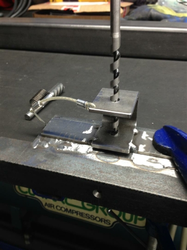
5) Insert the drill through the top, using the bottom of the C section as a guide.
As it is clamped in place it can’t move.
6) When the hole is drilled, remove the clamps. Voila’ one hole drilled perfectly straight and true, and at right angles to the rafter.
This is how it will work.
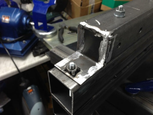
I decided to add an extra bolt between the angle iron and the cross member box section, just as an extra bit of security for safety reasons.
This will tie the steel to the steel, with a high tensile welded bolt.
This is the angle that the two angle iron side pieces will sit at, when attached to the cross member box section.
First of the two bolts, note that there MUST be flat as the rafter is going to sit over them.
First one welded into place,
This is how long the bolts will need to be to go through the box section cross member.
It’s now time to put it all together, so let’s go into the loft!
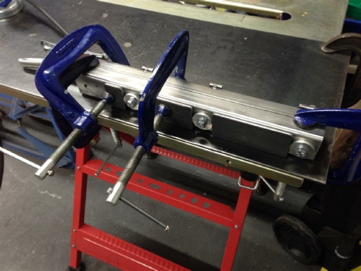
First we have to modify those rafters, by adding a second one to each side, and use those Ox Tool clamps.
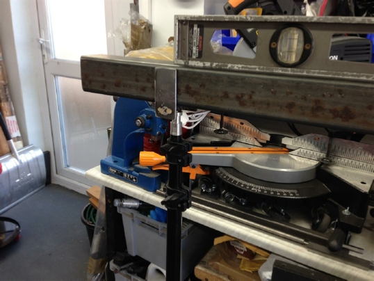
Remember those photographic stands, and those adaptors?
Well this is what they were for, the only bolts holding this lot together are the bolts we just welded in. The beauty about doing it this way is, as long as you don’t move it, it’s all aligned and holding it’s self in place. All we need now is that jig, and clamp it to the rafters, and this is now what we are going to do.
The OX Tool clamps were just a perfect fit over the top of the new rafter.
Notice the three plates used to spread the load over the two rafters.
Buy the right tools and you will not go wrong.
Now time for those 6 x 80mm TX Screwfix screws.
The TX heads were absolutely necessary as the screws required a lot of torque to drive them it.
But they worked very well in the end.
This is the actual template that I made to check that right angle and cross member alignment.
With the new steel work held in place on the stands, I added some wood screws to more securely hold the angle iron in place while I drilled those 8mm holes in the rafters.
Notice those Ox Tool clamps in use again? The spring and pin used to locate the jig into the right place in the hole that we previously drilled in the plate.
Pin and spring now removed, ready to drill the hole.
The DeWalt doing it’s thing with those brad point drills.
Swapping drills as the hole goes deeper through the double rafters.
Hole drilled and high tensile 8mm bolt now fitted.
Time to fit and drill that box section cross member in place.
The DeWalt drill is certainly paying for itself.
and lets not forget those dog washers.
The steelwork now all fitted.
I am very happy with the extra rafter idea, the angle iron and extra bolts into the box section cross member.
We now need to turn our attention to that hoist.
Now, you know me by now.
Never use something out of the box, if you can make it better!
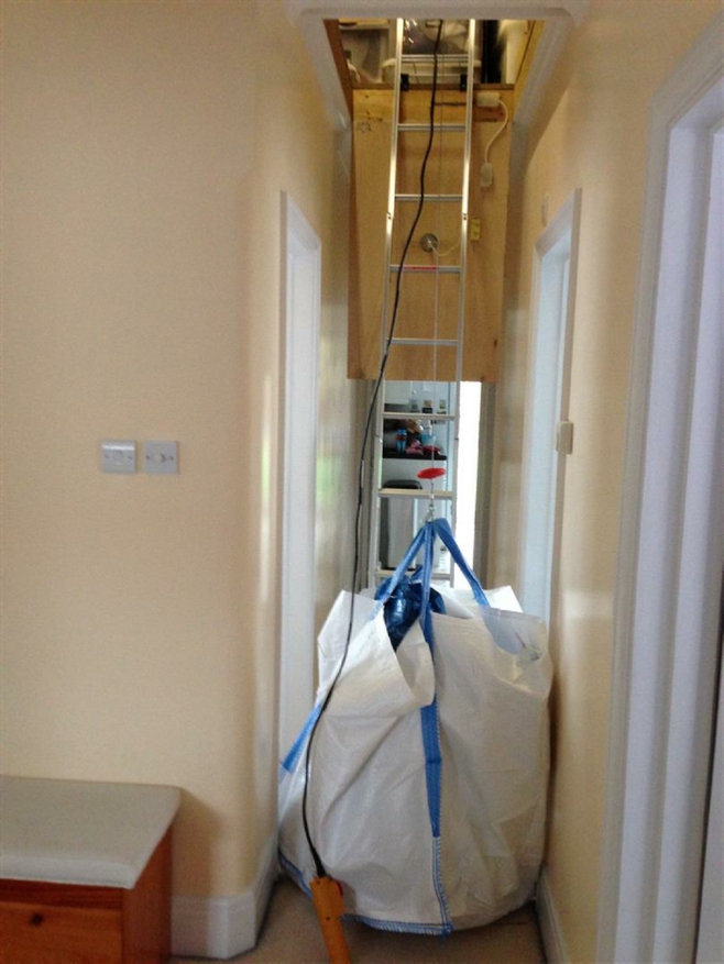
The hoist is supplied with a single controller, and a short cable. What I decided to do was bi-wire the hoist with a second controller. In this way I could have one controller in the loft, while the second one could be lowered through the loft hatch to control the hoist from the ground.
This would also work much better, if two of us are working together, one in the loft loading the hoist, and the other on the ground unloading it.
I purchased a second controller on Ebay, and had to change the phase capacitor, also found on Ebay.
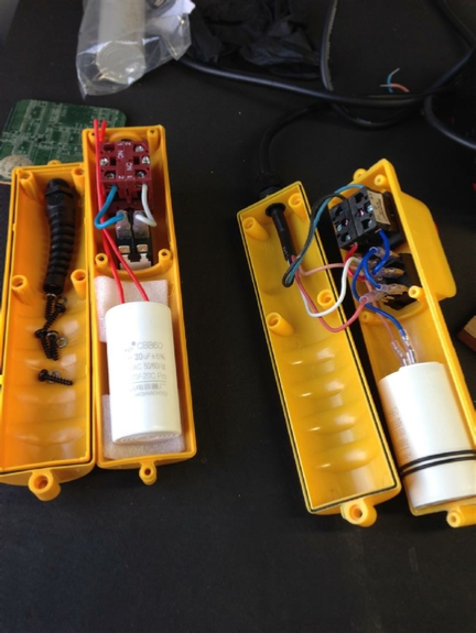
This is the second controller, with that capacitor now changed, all we need now is to add the multi way wiring.
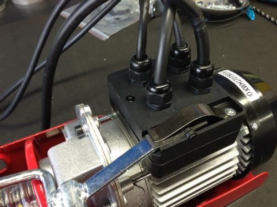
A new connection added to the original plastic connector block on the hoist.
I also added a second steel strain wire to the new controller, just in case the controller is dropped from the loft on to the floor. This will stop the electrical wires from being pulled out.
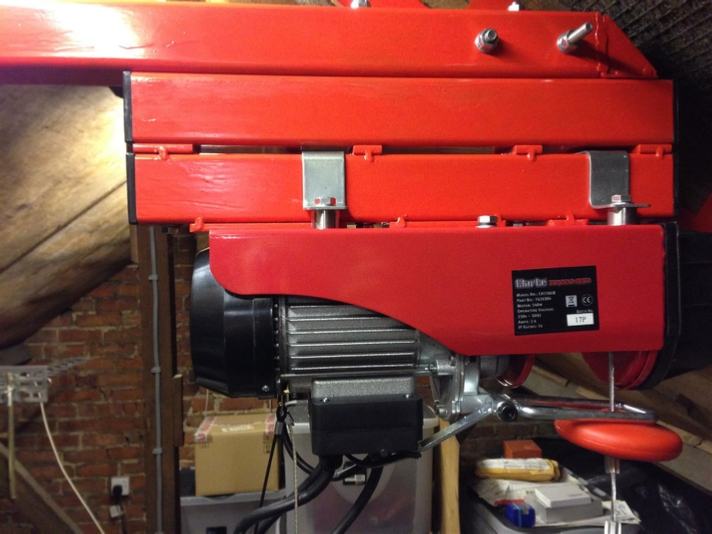
The second controller now wired in, and the hoist is now ready to go. We just need to build the mounting steel, that can be attached to what we have already fitted in the loft space.
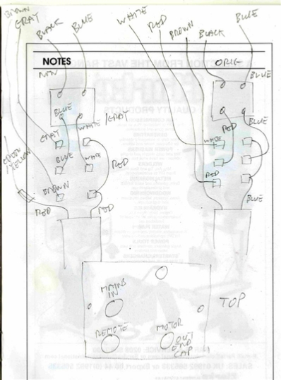
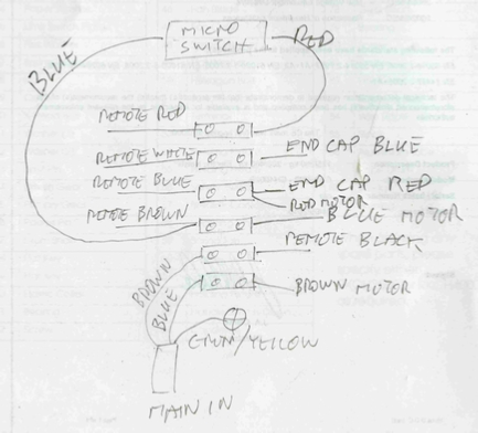
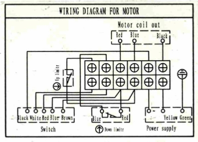
On the left is my wiring inside the hoist, above is the official diagram from inside the hoist.
The original controller wiring is on the right, with the new controller on the left.
It’s just a matter on connecting the new controller to the hoist, and you should be good to go.
Warning, DON’T use both controllers as exactly the same time in opposite directions, as sparks could fly!
This is what we are going to construct. I wanted to use long high tensile steel bolts to go the entire height from top to bottom to be absolutely certain nothing would move and it would be perfectly safe.
So let’s get started!
Time for a fit up. Having things on paper is all well and good but seeing it together is always much better.
The hoist clamps also need to be positioned, and for those to work we have to insert some spacers.
So this is how it should all look, when done.
All of these through holes need to be straight as there will be four long bolts holding it all together.
Notice the clamps and that roller stand?
Close up of the clamping.
It’s coming together.
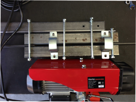
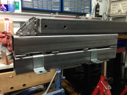
Test fitting the angle iron and cross member box section. We need to make sure that the hoist gearbox is going to clear.
More drilling and clamping.
Notice that Ox Tool clamp again.
The only way to drill a hole?
Fabricating that end bracket.
Notice one of those weldnuts.
There's always room for one!
The hoist brackets would not fit the 50x50mm box section.
So needed a little persuasion.
They seems something funny about using a Clarke's vice to bend a Clarke's bracket!
I had already decided to allow some back and forward clearance of the hoist on it’s box section mount.
So I could make some adjustment when the hoist was in place in the loft.
Hence the fitting of the clearance spacers, however one of the nuts attached to the fixing bolt was fouling the back of the black plastic gearbox.
So a little Dremel’ing was required.
I also made a spacing change, I now wanted to make sure that I could get a spanner into the gap above the hoist, and hold the nuts just in case I have to tighten the steel work in-situ.
I needed to make sure that I have 30mm diameter.
To get that 30mm I now need to shorten some on those 6mm steel spacer plates.
No problem, just wheel out that Cros_Arc 40 plasma cutter.
The cut was so clean, I don’t even have to debur it.
To make sure I did indeed, get those 30mm clearances, I turned up some aluminium 30mm spacers on the lathe and bolted them in place before doing the welding.
Now ready for the welding.
Spacers now welded in place, remember tacks only!
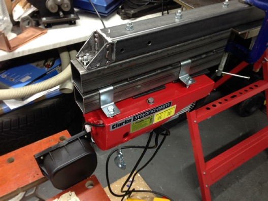
Now with the hoist in place.
I needed to check that sliding clearance, and all looked good.
The spanner also fitted!
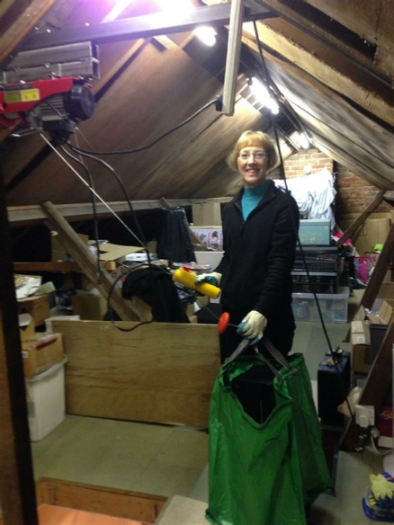
A quick dismantle, and a quick test fit for the first time in the loft.
I let Julia do the inaugural test flight!
I am thinking that smile on her face is because she is thinking about how much easer getting that Boot Fair stuff down is going to be!!!!!
The test worked perfectly, both controllers also worked, time for some paint I think.
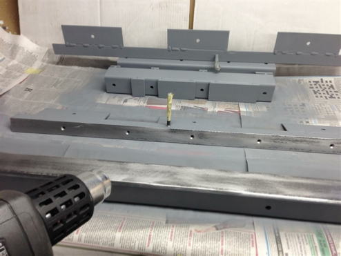
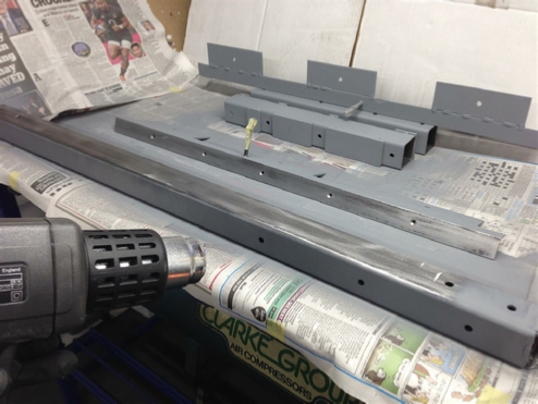
It’s now December and it’s cold in the workshop so I am trying to warm up the steel before priming it.
I decided to use etch primer because of where it’s going to be spending it’s life in the loft.
Time for a strength test, will it hold??????
And just to make sure, and no it did not move!!!!!
Still trying to warm it up and prime it.
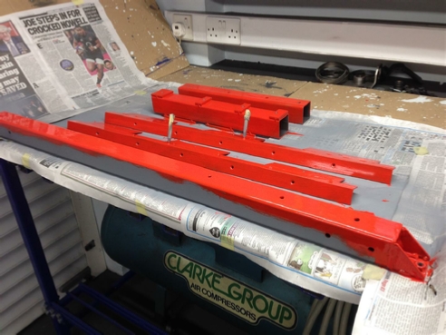
Well at least it’s time for some paint.
As you can see when I turned it over the paint was still not set.
Time for some rubbing down and repainting.
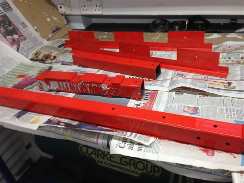
I hate this cold weather.
Still painting!
I wanted to fit some end caps, but needed a little work with the Dremel first, because of where the bolts had to go.
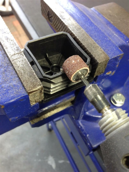
Just a little tip, slow the Dremel down, otherwise you will just melt the plastic, and not cut it!
That looks better.
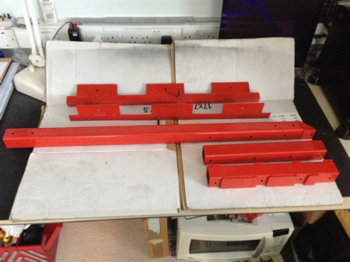
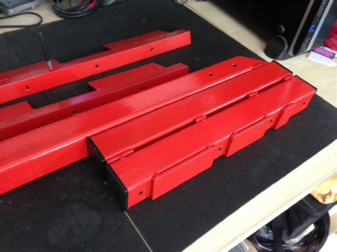
Paint now all dry.
and looking good.
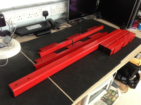
The finished result!
Just a small bag of things to go up?
The finished loft hoist.
If you have looked through this entire page, you might be wondering why bother with all of that welding, drilling, and fitting?
Why not just get a single, piece of steel, or maybe a length of steel pipe, couple of clamps, some screws at either end job done! Half the time and half the money.
Well first of all I wanted to be able to walk around in the loft an not bang my head on the cross member, so there must be an arrangement to set the cross member higher, and lower the hoist on one side.
I also do not want under any circumstances that hoist ever moving during a lift. Not being a structural engineer I always err on the safe side.
So far I have lifted into the loft, two power amplifiers, a large printer, an old microwave oven, the sort with a transformer, not the inverter kind, that is much lighter, all without any problem.
Oh, and also my plasma cutting guillotine, that I will be modifying later on, and that weighs in at 50 plus lbs, try lifting that into the loft by yourself?
Once we have cleared some space, I am also going to store my Rage 3 saw and the saw stand up there as well.
All made possible by this project, was it worth it, oh yes!
| Rage 3 Saw |
| ESAB Welder |
| Cros-Arc Plasma |
| HHO |
| Spot Welding |
| Betty's Gates |
| Car Headlights |
| Julia's Dartboard |
| Outside Light Base |
| Weather Vane |
| Geoff's Gates |
| Loft Hoist |
| Colin Laser Mount |