


Web Site by cg-photohraphy.co.uk


This is one of those projects that is absolutely necessary, when you need something that you just can’t buy, so you need to create it. I needed a small tool cabinet to fit a space, and you've guess it, it needed to have those wheels again!
I found a small drawer cabinet SL41B, where else but in Machine Mart, but because it was a side cabinet, which is purposed to be attached to a larger cabinet, they don’t have their own wheels or even do a wheel kit for it.
Check out the picture below.
Tool Cabinet Wheels
Project Date: 14 June 2018
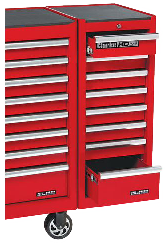
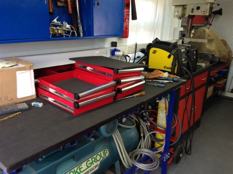
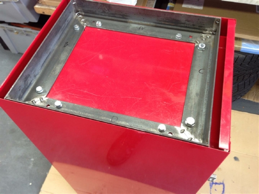
This is the side cabinet, you can see it attached to the full sized cabinet on the left, with it’s wheels.
What I needed was wheels on the side cabinet itself, and that is what we are going to do.
Now you know that I am always ‘banging-on’ about being sympathetic to what is already there, and that safety is always the main consideration.
In this design we have to consider both as paramount, so stay with us!
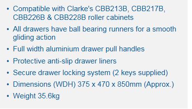
You will see from the design spec above that this cabinet weights in at 36Kg when empty.
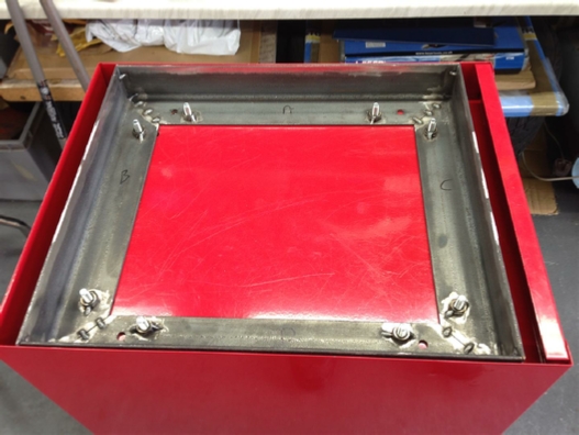
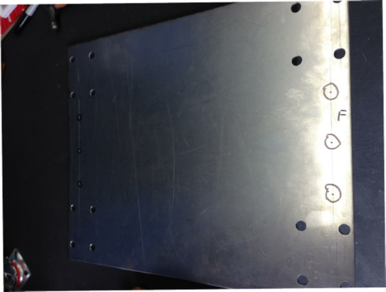
Now before I purchased one of these for myself, I had a look at one that was in the shop. I turned it upside down, and took some pictures, to try and get some idea about how to fit those wheels. Take a look at the pictures below:
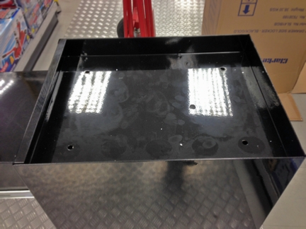
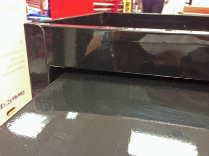
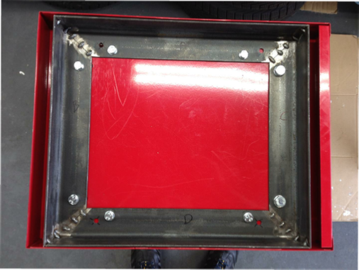
This is the view from the bottom. Notice the base plate panel, which is spot welded to the sides, it is the same gauge steel as the rest on the cabinet, so is NOT designed to take any sort of weight. We MUST bear this in mind?
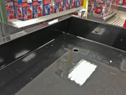
A better view of that panel.
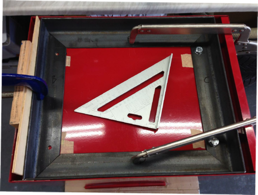
This view is from the front, with the bottom drawer pulled out to give me some idea of the depth that I have to play with for whatever I design for holding the wheels.
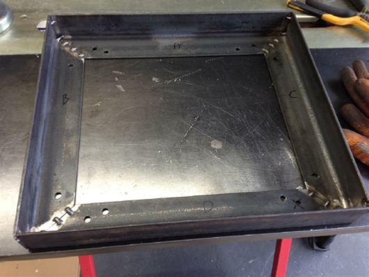
So what did the pictures above tell us?
1, We do not have any sort of lip to attach our wheel fixing panel to.
2, The bottom panel will never be able to hold the weight of the cabinet.
3, But we do have a reasonable amount of space to play with between the bottom of the drawer and the base, where the cabinet touches the floor.
4, The full weight of the cabinet is taken by the four sides of the steel on the cabinet.
These are our design criterion that we must take into consideration, when fitting those wheels.
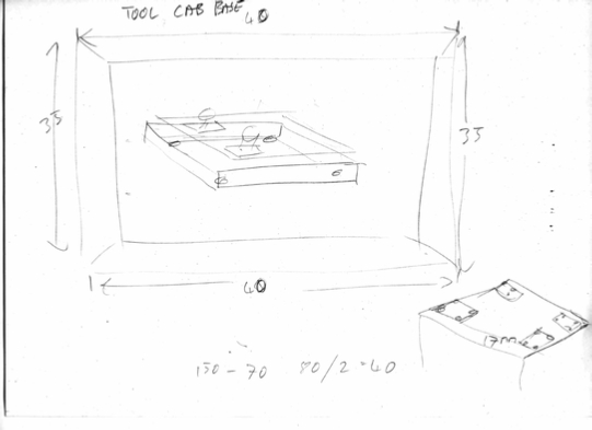
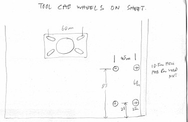
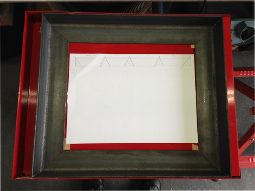
These are my detailed notes.
I have decided to use some 50x50x3 angle iron, cut to 45 degrees to form an oblong. Attached this to the spot welded cabinet base. Then and this is important, over cut the base metal by 1mm so that the sides of the cabinet will be take the weight on to the base and so through the wheels. This you MUST remember.
The base angle iron, I only had 1.5Mtrs so I had to get the cutting right first time!
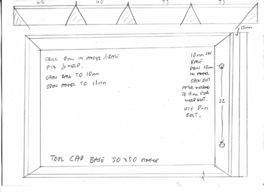
Notice the picture of the angle iron at the top of the page, with the cutting dimensions?
The wheels used four bolts to attach them to the base steel plate, which is going to be 3mm thick.
We are also going to use weldnuts to attach them, what else!
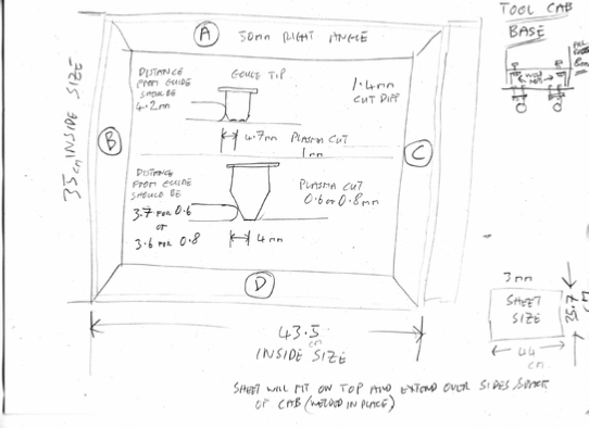
Now the picture on the left is where I had to accurately work out the cutting distance of the tips used in my Cros-Arc plasma cutter.
The torch that comes with it, is not some cheap throw away sort. It is one of the best quality Ergocut S45 touches made by the Italian company Trafimet.
As such uses high quality cutting, not only does this plasma system support gouging it also has a pilot arc and cut using this tip without a stand off from the metal it is cutting.
These dimension are going to be critical when we cut the wheel sheet, as it MUST give us exactly a 1mm overhang to take the cabinet weight for safety reasons. I also only have one sheet of steel so it has to be right first time. A lot to ask from my Cros-Arc 40!
So let’s get started:
First get those drawers out.
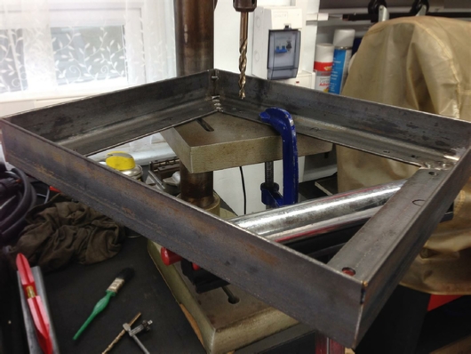
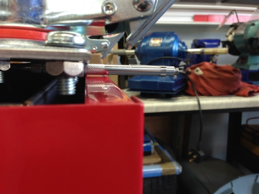
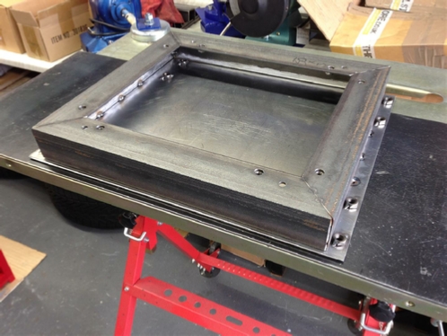
Let’s do a fit up just to make sure our ideas are going to work.
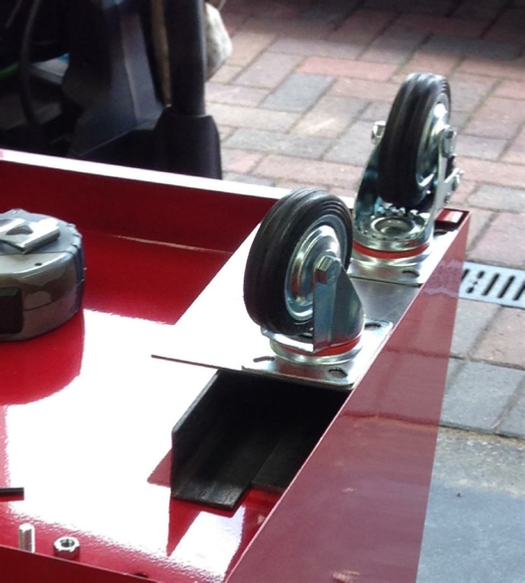
A closer look. Notice that the 50x50m angle gives us just the right amount of clearance for the overhang.
Sometimes you just need to get lucky!
Looks good!
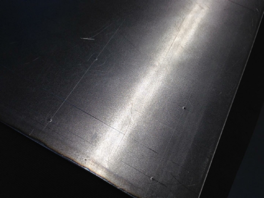
I set up a guide, took into consideration the distance between the plasma guide and the cutting centre of the plasma tip, set the Cros-Arc at 40Amps and kept my fingers crossed.
Did I need to do that? No of course not, the Cros-Arc did its thing perfectly. See Below:
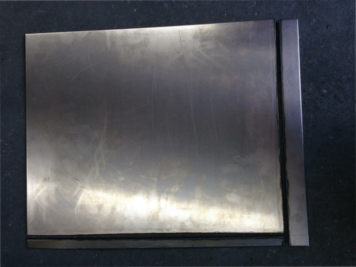
A perfect cut on both sides, accurate to 0.5mm, just what I needed.
Let’s take a look at the fit, see below:
And now a perfect fit to the cabinet base.
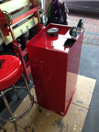
Quick test fit for those wheels.
And what about that overhang?
Just right!
Its now time to get that Rage 3 fired up and cut that angle iron, remember also no room for error as I only have one length.
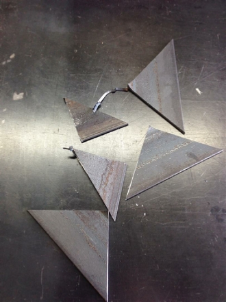
This is all that’s left, having made those 45 degree angle cuts, from a 1.5Mtr length
The cut angle now fitted into the bottom of the cabinet.
Looks good!
A quick look at how much space we have for those weldnuts at the back, to attached the wheels.
Looks tight?
It also looks just as tight from the front. We will have to be very careful how we mark and drill those holes for the wheels and weld those weldnuts in.
Right now, let’s get that frame welded together, and don’t forget that time from the last project, about using that air gun. What we don’t want to do is damage the paint on this cabinet either. So with the welder and the compressor fired up let’s get going!
I placed the front piece in place and then drilled two mounting holes, placing two temporary bolts in so that I would have a datum point to clamp the rest of the pieces too.
Then started to tack weld and apply the air gun, one tack at a time, remember?
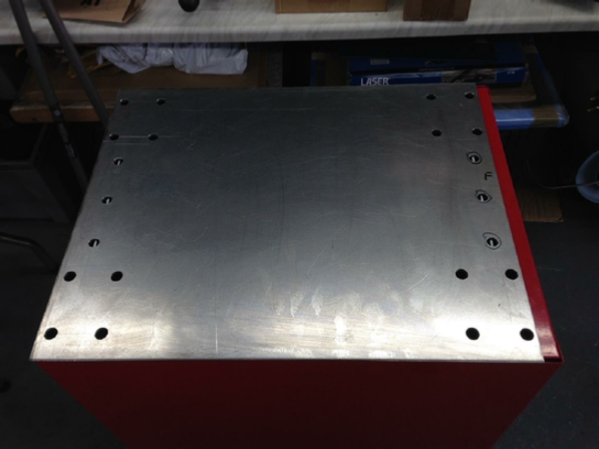
All the corners now welded, and mounting holes drilled in both the base and the angle, and test fitted in place.
So Far, so good!
We now need to increase the hole sizes for those weld nuts.
Notice that extended roller stand holding the base unit level, and the fact it is clamped, remember we want round holes for those weld nuts not ovals, as they MUST line up with the holes in that we have already drilled in the cabinets base plate.
Weldnuts now welded in place, and fixing bolts holding in in place in the cabinet.
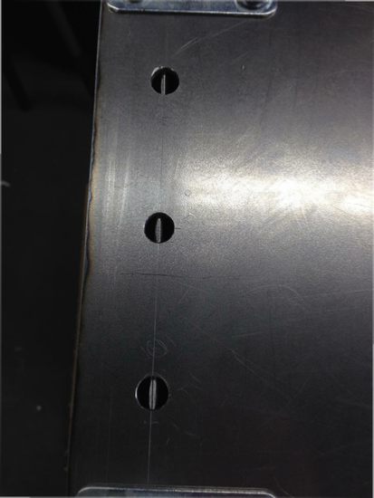
Time to accurately mark out the wheel mounting plate, remember how tight for space those weldnuts are going to be.
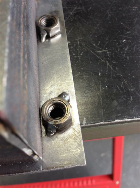
Quick check before we go to ‘mad’ with that drill?
Well that nut looks tight for space, welding that weldnut is going to be fun!
All four wheels now test fitted.
How are we going to attach that wheel plate to the right angle frame?
For the plug welds, we need to make out and drill some holes in the wheel mounting plate where the right angle frame will be.
Drop the plate in place and check the alignment.
Back looks good!
And so does the front.
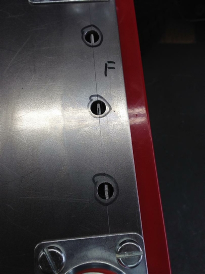
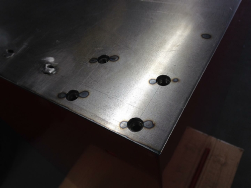
Ready to weld those wheel weld nuts.
Weldnuts now in place, and welded.
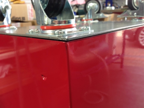
This shows how tight a fit those front wheel weldnuts are!
and that plate gap to the cabinet sides. Remember the sides of the cabinet will take the full weight, a gap of 0.5mm is just fine.
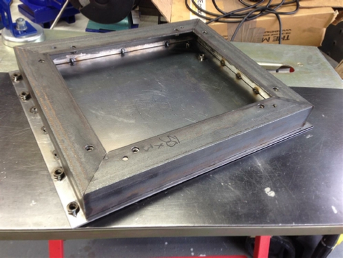
The finished frame.
Take a look at it, what do you see?
or what do you NOT see?
Tack welds, equals no distortion!!!!!
Right?
No distortion, equal perfect fit!
Plenty of penetration for the wheel weldnuts.
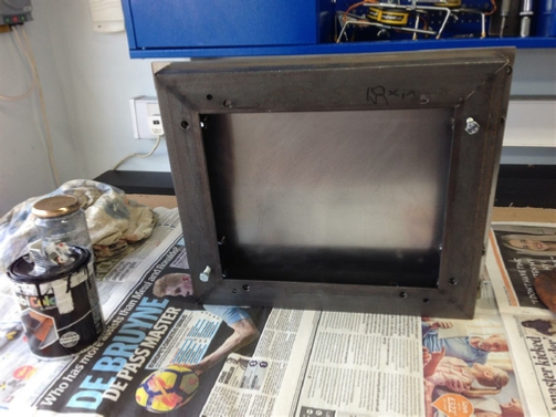
The finished wheel mount frame and new base plate.
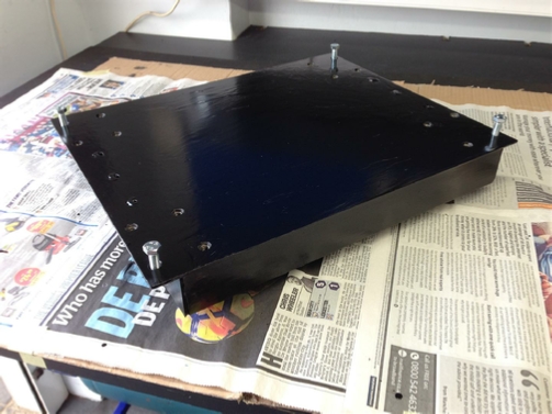
Getting ready to paint.
Looking good!
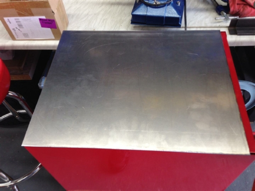
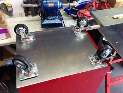
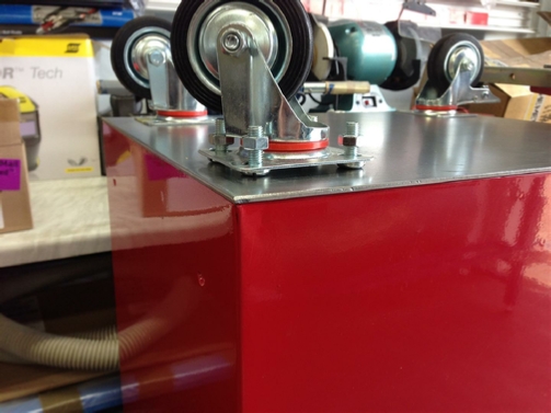
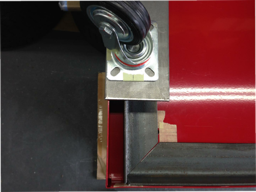
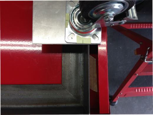
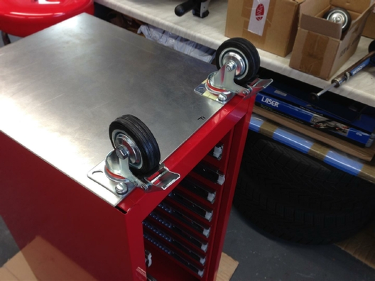
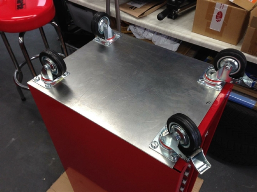
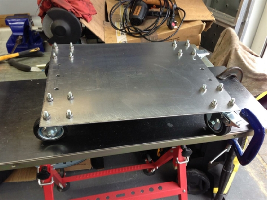
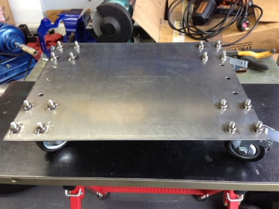
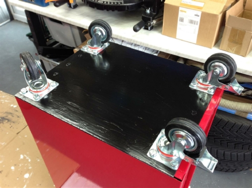
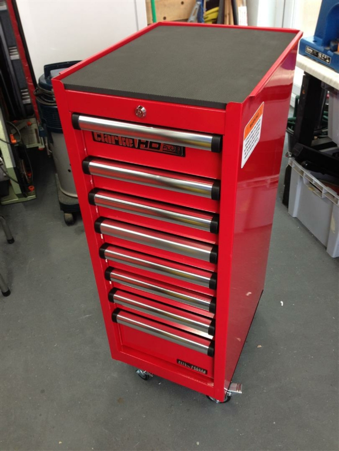
Bolted to the bottom of the cabinet, with the wheels fitted.
The finished cabinet, standing on it’s own wheels, ready to be filled with tools.
To date, I have not had any problems using or wheeling the cabinet around.
I also had no paint discolouration on the cabinet, from welding the angle in situ, using the Air Gun technique.
Only one word of caution, as this cabinet is tall, care has to be used when moving it!
Another project done!
| Rage 3 Saw |
| ESAB Welder |
| Cros-Arc Plasma |
| HHO |
| Spot Welding |
| Betty's Gates |
| Car Headlights |
| Julia's Dartboard |
| Outside Light Base |
| Weather Vane |
| Geoff's Gates |
| Loft Hoist |
| Colin Laser Mount |