


Web Site by cg-photohraphy.co.uk


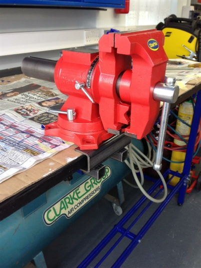
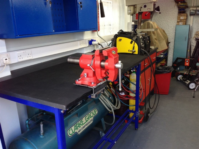
What I needed was a heavier duty bench vice for those occasions when you just need a bigger vice. Now I had seen a vice that had a four point fixing at the base, and two side clamps, which was just what I was after. Including the ability of a full 360 swivel, both horizontally and vertically.
If you have read the last section on the Equipment page you will know what I am talking about.
So in the end I did purchase the Clarke’s vice from Machine Mart and it was the correct one.
I now needed to make a mount, no problem I hear you cry, well yes there is, because this vice not only weighs in at whopping 44lbs, two of its fixing holes need to be actually in the box section that goes over the bench top, and my mounts weren’t actually designed to have these fixings placed at that point.
Now I bet you are thinking, why?
Well let me tell you, if you make something whether it is a restoration project or a mounting a piece of equipment you must always be sympathetic to what is already there.
In this case it is a very important safety feature.
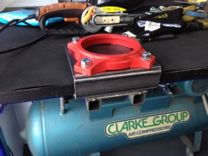
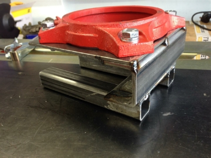
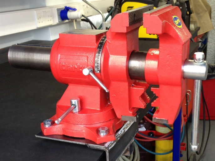
If you look at the pictures above, which incidentally is my first mock-up, to test the water so to speak. You will see that when the vice is placed in this position, it is balanced. This means that the mount is not stressed. If the vice was placed further back, all of the mountings, including the front cross member would be under a load, other that just its weight. The stress would be a turning point load.
Now I am not saying that this load will not show up under use, especially when you open the vice jaws up and grip a work piece. But why not start in the best position in the first place?
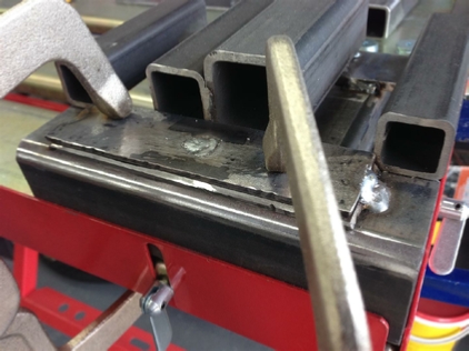
So my design not only had to be stronger, but I had to accommodate those weldnuts for the mounting of the vice bolts.
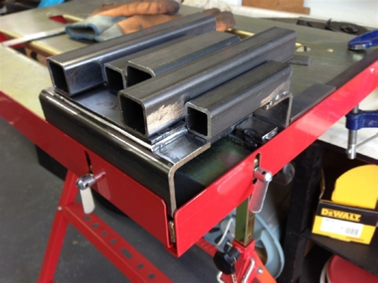
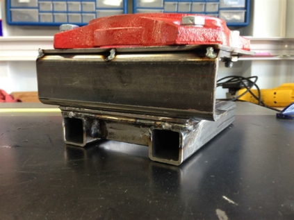
In the picture above, you will see that I have added two 4mm steel plates. This will raise the U- shaped mounting bracket, allowing me to get the weldnuts into place. One problem is how am I going to join these two plates together, and fix them to the U bracket?
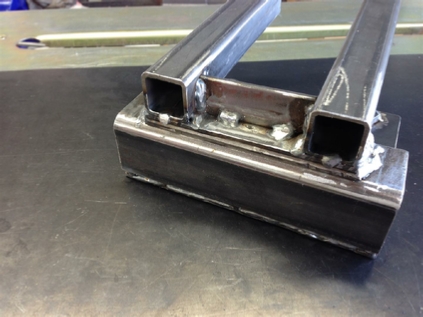
You will see in this picture that I have added a front cross bracing plate to give further rigidity to the quick release mounting.
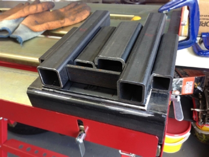
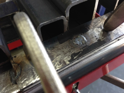
So did you work out how to attach those plates? Simply drill two sets of holes in different places in both plates, and use a simply ‘Plug-Weld’, easy.
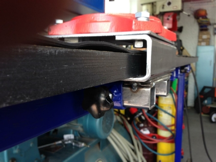
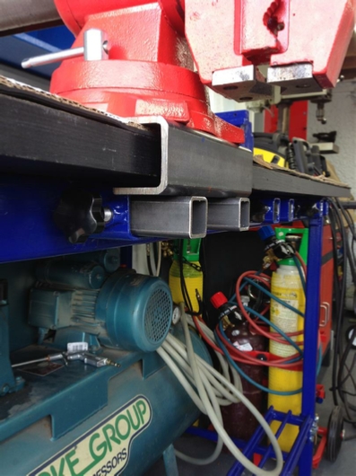
This picture shows the HD mount now welded and being test fitted.
This picture show that extra clearance that I created by welding in those extra two 4mm plates.
HD Vice Mount
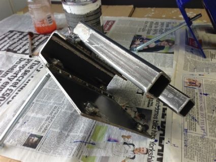
The finished mount ready for painting, red of course!
Another project done!
Project Date: 16 June 2017
| Rage 3 Saw |
| ESAB Welder |
| Cros-Arc Plasma |
| HHO |
| Spot Welding |
| Betty's Gates |
| Car Headlights |
| Julia's Dartboard |
| Outside Light Base |
| Weather Vane |
| Geoff's Gates |
| Loft Hoist |
| Colin Laser Mount |