


Web Site by cg-photohraphy.co.uk


I guess there are two main design criteria's for the bench, the second one is that the bench can remain completely flat and free of clutter, including vices and bench grinders. To this end I needed to design some sort of quick release mounting system. Heavy duty enough to hold the largest vice but be completely unobtrusive when not in use. I took a long look on the Internet to come up with some ideas.
Quick Release Mounts
Project Date: 24 April 2017
I wanted a design that would not allow the mounting plate to turn, so a tandem slider system was going to be used.
I also needed the front of the mount to go over the top of the bench, as I was going to use weldnuts for securing the device, this also needed to be taken into account.
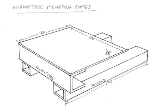
I decided on the following:
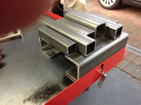
Front top 50x50x5 box section. Plasma cut off the rear section, create a U shape.
Top mounting plate 18cm x 16cm x 4mm
Bottom inner sliding sections 3cm x 3cm x 3mm
I had the The Metal Store cut all of these parts to size before delivery.
However, first things first. Because ALL of these mounting plates MUST be able to fit into all of the (three) bench mounts, it was imperative that they all be exactly the same.
The only way that that can be achieved was to create a jig, so that they can all be assembled in the same way.
First job was to set up and try out my new Cros-Arc plasma cutter, this story can be found here, on the Equipment/Cros-Arc Plasma page.
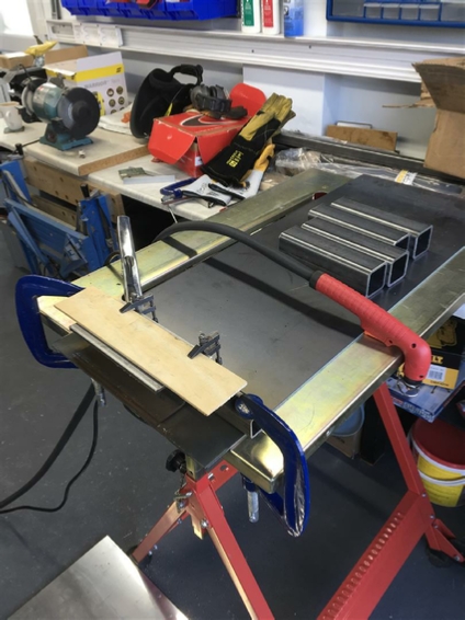
I set up the following, using a 4mm steel plate to try and protect my welding table and that stainless steel splash back on the floor.
I clamped a length of box section down with two G-clamps, as per the picture on the left. I then clamped a wooded guide to the top using a pair of tool makers clamps, very carefully setting up the required front to back depth for my cut. In this way I could do cut, after cut, exactly the same on all of the pieces of box section that you can see behind the plasma cutting touch. All I had to do was slide each piece in, and cut it.
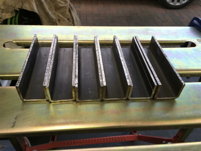
This idea worked very well enabling me to cut all of the box sections exactly the same.
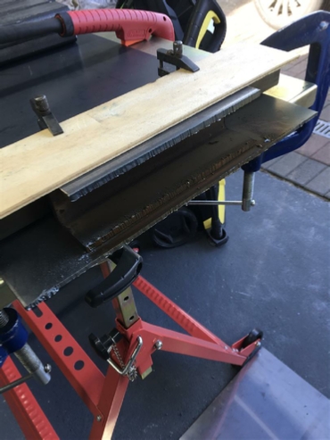
As you can see the results are excellent from the Cros-Arc 40 plasma cutter, all I had to do was run them over very lightly with a 120grit flap disc. Very pleased with the plasma cutter, and the results!
Now back to that Jig.
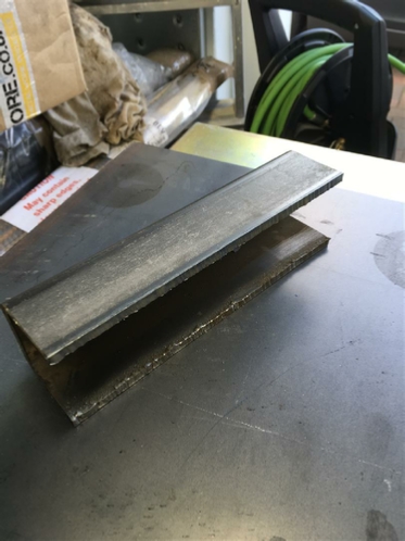
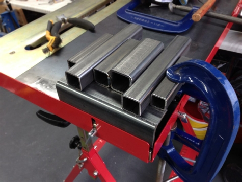
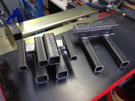
This is the first part of the mount jig being welded. I am trying to align the six pieces of box section up to give me the correct spacing that I needed.
Notice the two different size pieces in the centre.
I needed this spacing to be exactly 7cm.
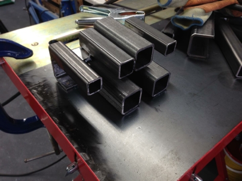
…and yes I know it looks like the Star Ship Enterprise.
..and no, it was not intentional.
But it is a nice touch!
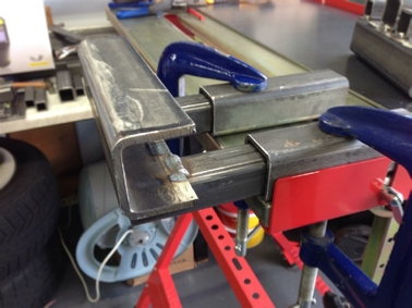
In fact as you can see, when in use, it actually sits upside down! This allows the right depth for the sliding arms to be set at the same time.
Sorry about my thumb in the picture.
First mount welded using the new jig.
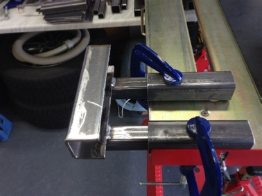
The mount here is also being tested for slide-ability!
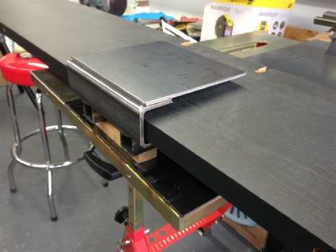
The front section being also tested for depth, using the back section of wood bench top.
Remember those weldnuts must clear the bench top.
All in all another successful project concluded.
I now have a working jig so that I can create identical removable mounting plates for all of my bench mounted devices.
On to the next, one!
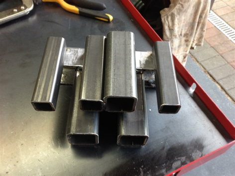
The finished jig!
| Rage 3 Saw |
| ESAB Welder |
| Cros-Arc Plasma |
| HHO |
| Spot Welding |
| Betty's Gates |
| Car Headlights |
| Julia's Dartboard |
| Outside Light Base |
| Weather Vane |
| Geoff's Gates |
| Loft Hoist |
| Colin Laser Mount |