


Web Site by cg-photohraphy.co.uk


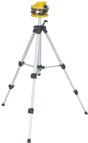
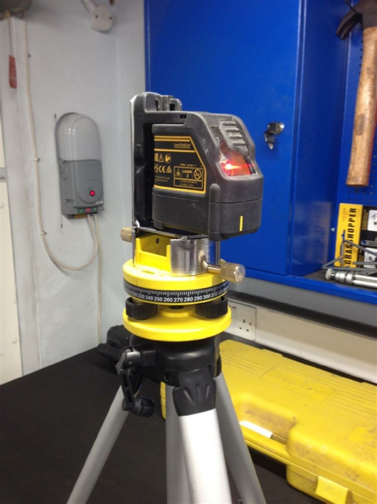
One of my neighbours Colin, asked me to design and build for him a mount, so that he could use his DeWalt laser measure on a Theodolite base that he had.
I thought at the time this would be fairly straight forward, a simple L-shaped bracket fixed onto the top of the base unit, then use the magnetic side mount on the laser to attach it.
Colin Laser Mount
Project Date: 18 Dec 2018
However, when I took the base unit apart I found that not only was the base unit not solid, it was actually made of white metal, which is very soft. So soft in fact that the two areas used by the unit to attach the mounting screws was actually reinforced by the metal being thicker in these places.
In reality this means that I would be forced to use these same mounting points.
The main problem was that they were on the rounded sides of the unit. How do I create a mounting for that?
The only answer I could think of was another ring.
That ring roller is certainly coming in handy.
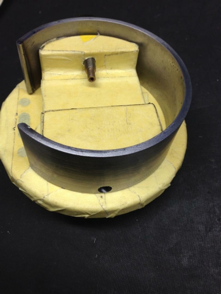
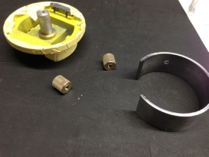
This is a view underneath the mounting base.
I have protected the base unit by covering it in tape, just in case you were wondering.
You can see the reinforced screw fixing hole on the left.
I have two problems:
How do I transfer the hole position from the base unit, onto the new steel ring?
The holes that I drill in the new mounting ring need to be tight, because I do not want the mount moving when the laser is placed on the new bracket we are going to fabricate and then weld to the new ring mount.
That hole mounting accuracy needs to be spot on.
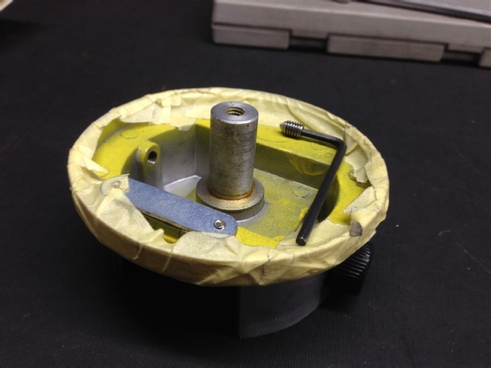
If you have a look at the picture above, you will notice a small stainless steel grub screw, that has been sharpened to a point!
The idea being, drop the new steel ring onto the base, put the grub screw into the base from the inside, give the ring a tap with a hammer from the outside to mark the inside of the ring.
Are you still with me?
Then transfer that position from the inside to the outside, use a centre drill on the drill press, then drill a 5mm hole, and then hope it all works out.
Well this is the plan!
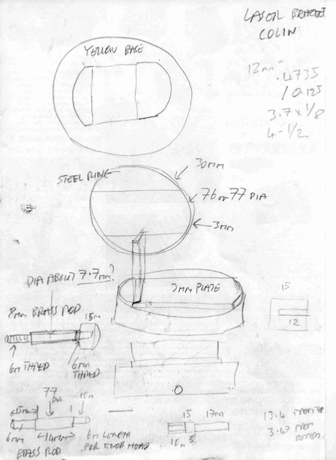
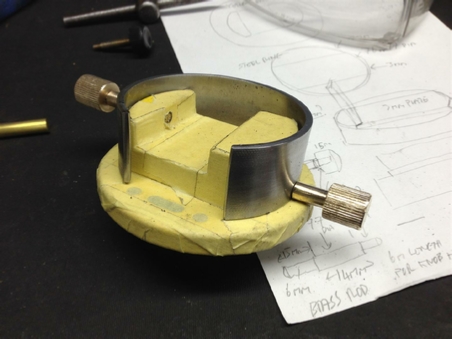
My notes and the plan for this project.
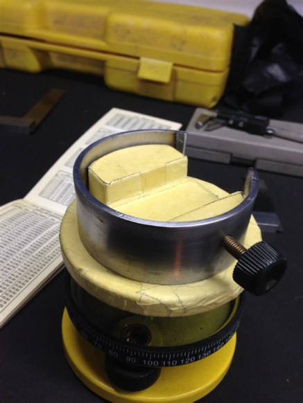
I rolled the complete ring, then decided to cut the ring on one side, because the base had a spirit level built in, and I wanted this to be visible, when the base was in use.
No problem to fix this with the Cros_Arc plasma cutter.
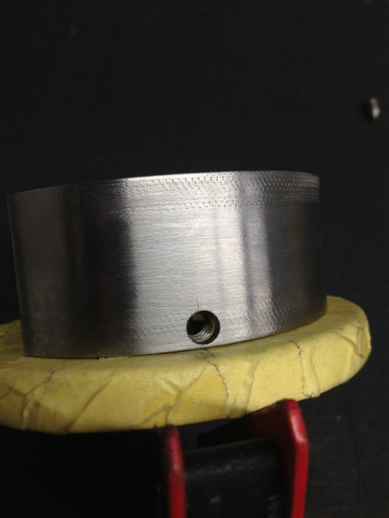
Also that first mounting hole worked out really well. See opposite.
Only problem was that Colin only had one mounting screw, and the screw on the other side has virtually no clearance on the base unit.
See what I mean about that clearance? It was less than 1mm.
This was the second hole, looks like my marking out skills are holding out ok.
This was the only screw that I had, so it’s time to find that brass rod and get the the lathe wound up!
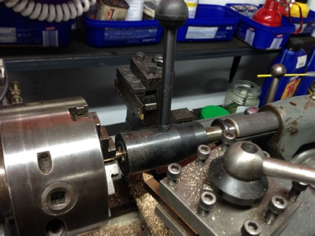
Screw cutting on the lathe, using the screw cutting attachment.
Two screw ends made.
Both screws now finished and screwed in place.
I got out the trusted Cros_arc and plasma cut a top for the ring, using 3mm steel plate, and then a back piece to form an L-shape. Then welded all three pieces together. See below.
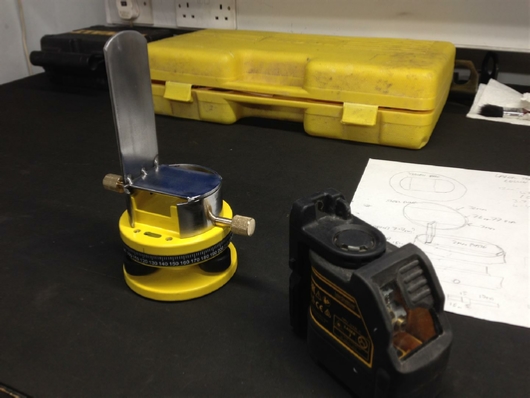
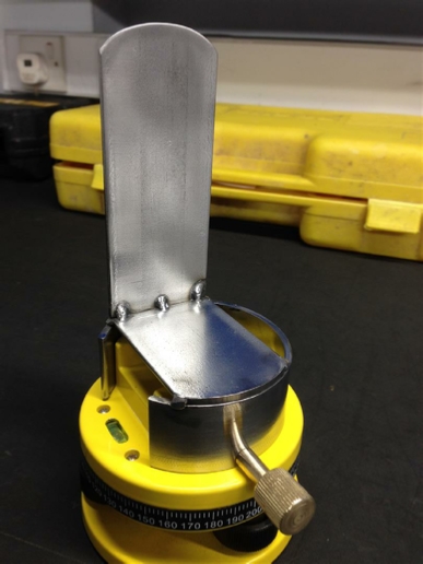
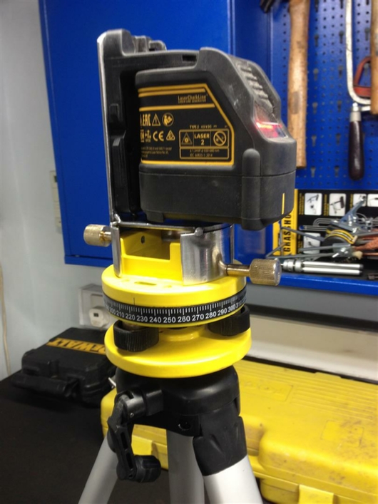
I decided not to paint the mount, because the magnets on the DeWalt laser was so strong, it would simply scratch it to hell. Instead I polished all the surfaces on the linisher, and added a coat of protective wax. Colin was happy with the finished mount.
Another project completed.
This is the paper template that we are going to use. The steel will need to be this size to make the ring that will fit over the base.
| Rage 3 Saw |
| ESAB Welder |
| Cros-Arc Plasma |
| HHO |
| Spot Welding |
| Betty's Gates |
| Car Headlights |
| Julia's Dartboard |
| Outside Light Base |
| Weather Vane |
| Geoff's Gates |
| Loft Hoist |
| Colin Laser Mount |